The natural ELF/VLF radio signals I want to receive are essentially those of the audio frequency range (perhaps going a little lower, so call it 1-20kHz). If you act as an antenna yourself and plug yourself into an audio amplifier by putting your thumb on the input lead, the signal you will hear above anything else is mains hum (50Hz Europe & Australia, 60Hz US). The natural signals are way weaker than this, so if I want to use the receiver even remotely near power lines, I need to get rid of that hum.
While it would be straightforward to cut 50Hz using a digital filter, the level is so relatively high that it will swamp the desired signal going through an A/D filter leaving little useful resolution. There’s also a good chance of it saturating any analog pre-amplification.
It’s worth noting here that the mains hum tends to be pretty dirty, with lots of harmonics (2x50Hz, 3x50Hz etc.). According to Radio Nature the big ones are the odd harmonics. But for now I’ll just try cutting the fundamental, see if that’s enough.
A related issue is that the natural radio signals are of such a low amplitude that noise generated by the receiver circuit components may also be an issue.
So I’m thinking, whether I use a coil (for the magnetic component of the natural signals) or a free antenna (electrical component), I should first have a little fairly wideband but low noise pre-amp, maybe x10 or x100 to minimise noise addition later. Have this followed by a notch filter and then further amplification to get the signal up to line levels.
The standard simple filter is the twin-t notch, more or less a low pass and a high pass filter bang up against each other. But the notch with this isn’t very sharp. This can be improved by throwing in a couple of op-amps, as in this circuit :

So I tried this on the breadboard, only with approximate values (33k rather than 31.8, 5% capacitors).
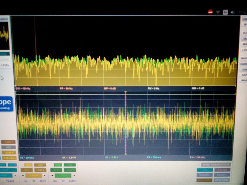
 This didn’t appear to be working, with white noise as input, the scope showing freq domain trace (top, marker line is 50Hz) :
So then I just tried the passive twin-t, and got a similar result 😦 I guess the noise input/freq domain on scope is a losing combination.
The BitScope has a basic signal genenerator built in, so I tried that on the passive circuit:

Here there is a distinct difference between the input (green) and output (yellow) at 50Hz compared to other peaks.
Reassembling, I tried the active circuit with the sig gen :

Boo, no significant difference. But I strongly suspect this is down to measurement fail again. The sig gen is very limited, only offers 50Hz, 100Hz etc, and even if the components in the filter were perfect, the notch would be at 48Hz. Allowing for tolerances, it could be way out. But assuming the active circuit is working, there could be a sharp notch at say 45Hz, relatively flat at 50Hz.
So next step, I reckon I’ll knock together an analog sig gen, hopefully get a clearer view.


