tl;dr : the circuit seems good for high frequencies (low inductance) but for low frequencies is very dependent on the emitter current. Probably suitable for use in an inductance/capacitance meter for radio work (when coupled with a freq counter).
I did a little video.
Here’s the version I breadboarded :
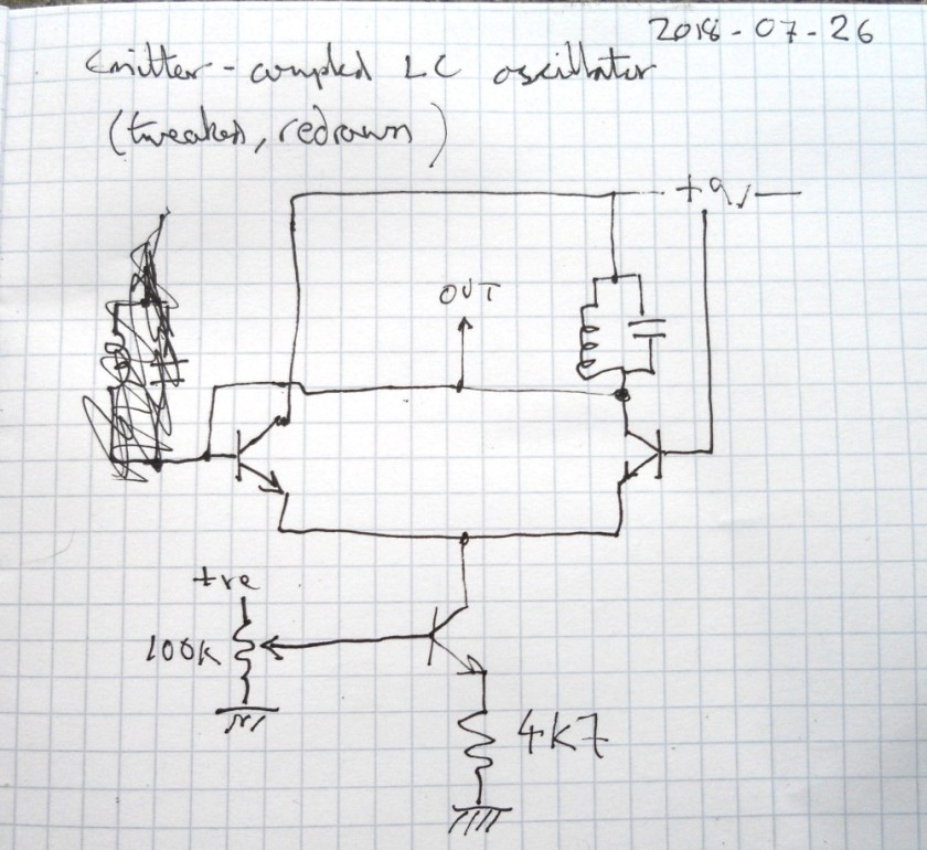
Here’s some analysis.
For the resonant tank I tried both the primary of a little audio transformer + 10nF and a hand-wound coil + 1nF.

For the transformer + 10n, the frequency was around 850Hz, but varied a lot dependent on the current to the emitters. With about 0.7v from the pot, 30uA at the emitters, it produced a reasonable-looking sine wave (if you ignore the noise, that’s presumably just from my test setup):

Upping the voltage, and hence emitter current, distortion of the shape soon became evident (along with a significant increase in amplitude and change in pitch), until at around 3v – er, and a lot more current, I forgot to write it down, the wave looked like this, more like wonky relaxation behaviour:

For the coil + 1n, around 0.7V at the pot, 30uA at the emitters, it produced what looks like a pretty good sine wave at around 110kHz :

Upping the voltage again, there was still a big difference in the amplitude, but nowhere near as much in frequency. Also there looks to be considerably less distortion:

Now by my reckoning, given that the resonant frequency is 1/2*pi*sqrt(LC), this should make the inductor 2mH. In theory it should be possible to estimate the the inductance by the coil’s physical characteristics:
turns : 45 (or thereabouts)
wire diameter : 0.4mm (ditto)
coil diameter : 20cm (ditto)
But when I tried the formula here (estimating the coil length as 1.8cm), I got 55mH. Not even ballpark. I’ve tried a few online calculators but alas they seem about as reliable as my arithmetic, getting values that differ by orders of magnitude.
So I double-checked my algebra, rearranging the formula step by step, producing :
L = 1/C*(2*pi*f)^2
This again gave me a result of 2mH.
Googling a bit more, I found this page with some practical examples, including :
  L uH  Litz Size Turns Coil Width  Q-1.6MHz  Outside Wire Holes
  238    165/46    47    1-7/16       770     15/16 inch from each end
The inductance formulae on Wikipedia suggest that the induction is proportional to the square of the diameter of the coil. Which (flipping the above into cm and squaring) gives a ratio of 13:400. Leading to an inductance of 238*400/13 = 7323uH = 7mH. That’s getting more ballpark.
But it gets better – the inductance calculator linked from the page with that formula uses a completely different formula, with factors more like those I’m looking at:


Yay! Near as damnit 2mH!
PS. Hmm, one thing I’d forgotten with the above calculations is the self-capacitance of the coil. Turns out that without any parallel capacitor the circuit oscillates at around 190kHz.
Frequency is proportional to the square root of the capacitance, so doubling the frequency is like quartering the capacitance…so if my head isn’t overly scrambled by now, that would give give a self-capacitance very roughly in the region of 250pF. That feels about right, picturing the total area of those 365pF variable caps.
I’m tempted to try out a better-known LC oscillator like the Colpitts, and draw some graphs of results, buy some precision capacitors and inductors, design an Arduino-based LC meter… But this has already taken loads of time and is veering well away from what I should be doing (ELFQuake proper, something towards work-work, or even tidying the kitchen).
Fun though.
