Happy New Year!

A good time to take stock, huddled in front of the fire.

Boo!

As is often the case, I’ve been moving more slowly on this project than I’d have liked. Lack of resources is a continuing problem, but my own tendency to procrastinate has been by far the biggest obstacle to progress. On top of this, my main dev computer packed up recently, so until I can get that fixed or replaced I’m getting things set up again on an old laptop. Frustrating.

Three Steps Forward…

My strategy of taking a multi-pronged approach has had its pros and cons. I’ve got a prototype VLF receiver mostly built and have spent quite a lot of time playing around with Arduinos and related devices. On the software side – which is really the novel aspect of this project – I did make reasonable progress, getting together a provisional system design and some of the implementation. But then stalled. My desire to build hardware to allow local data collection has been something of a distraction, when there’s nothing stopping me from working with data from INGV and VLF.it.

Plans.

Looking ahead, I really need to reboot myself on the software dev. The ultimate target for running code will be nothing more sophisticated than this laptop. But for exploring algorithms and probably NN training, pre-optimisation, I reckon using cloud services will be my best bet. Concurrently I can look at some of the side prongs that I want to include in the system as a whole – notably web publication of data and automatic generation of Twitter notifications.

As everyone that’s worked on a solo project knows, I’ve also got a lot more material in my head or at best sketched in notebooks that needs writing up. How often has the New Year Resolution been : “Write more docs.”.

Mini-Seismograph

On the hardware side, until I’ve got my income a bit better sorted out I am pretty much limited to rather a scattergun approach using what ever components I have at hand. As well as finishing off the mostly-built VLF receiver, I’ve also got the bits for a basic seismograph. It’ll essentially be :

  •  ESP32microcontroller + comms :  core of the subsystem, handling the acquisition and preprocessing of data, which it will expose using a basic web server, accessible from the local network (the ESP32 includes WiFi connectivity).
  • MPU6050sensors : accelerometer +gyroscope : a tiny MEMS device, connected over I2C.
  • MicroSD carddata logging : experience shows that 100% connectivity is implausible, so some local history is very desirable
  • Tiny RTC cardrealtime clock :  the comms will be async, so accurate local timestamps are a must.

The ESP32 is a remarkably capable little device and I’m reasonably confident of the viability of interfacing the peripherals. Hopefully just a matter of plodding through example code for each, tweaking as needed.

The MPU6050 sensors are much less sensitive than those of typical seismometers. Only events with significant magnitude are likely to be detectable. It remains to be seen, but I have my suspicions that having 2 different types of sensor in there mean it will, with a bit of wrangling, be possible to get more effective sensitivity than the individual sensor data would yield. Whatever, once the wiring and code is in place for this setup, it should be trivial to extend it to use a more sensitive sensor. (Note the Raspberry Shake 4D configuration.)

Also…

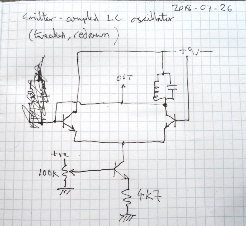
I’ve got a little tangential project on the go. ELFQuake is in essence about trying to model aspects of a physical system : Earth geology and its electronically-detectable artifacts. Creating an analogue in software that captures enough to be able to make useful predictions. Also I’m increasingly convinced that the design of analog circuits between the sensors and standard data acquisition elements (ADCs etc) will have a major impact on the potential success of the system. Putting these points together, it shouldn’t seem that off the wall that I’ve been working on the design of an analog computer. (I must admit I also want to play with chaotic systems, this is something I’ve been messing about with for years).


VLF Receiver Oddments

I’m doing a little more on a simple handheld VLF receiver I’ve been working on. For an electric field receiver all that’s essentially required is a whip antenna and a high input impedance, high gain, audio frequency amplifier. Some filtering is desirable to limit the bandwidth and cut the noise of mains hum.

I’ve already soldered up the input & filter stages, yesterday breadboarded the output stage – an amplifier to drive a little speaker/headphones. But I’d forgotten a key consideration, how much overall gain the thing should have.

A quick google later, found this rather nice poster on NASA’s site, “Building and Testing a Portable VLF Receiver“.

Screenshot from 2018-08-28 18-54-27

It doesn’t have the schematic – I expect it’s one of their INSPIRE models. But it does have what I was looking for. Signal is of the order of microvolts, their overall gain is x1500 – rather more than I’ve allowed for so far. There’s a feedback resistor change in my near future.

First though I reckon I’ll draw up the circuit as it stands (in KiCAD). I can figure out the gain bits from there, and simulate. I also need to check roll-off at the frequency extremes (call it 20Hz & 20kHz). Hmm, gain of 1500, that’ll be tempting to stability problems.

When I was looking for the gain requirements yesterday, I opened a bunch of the results in browser tabs. I found what I was looking for in the first, but am pleased I didn’t close the others. While vlf.it is the site for all things Radio Nature, I did stumble on some material I hadn’t seen before.

This page is notable : VLF Natural Radio Reception at techlib.com. It features a variety of simple receiver designs. One piece of utter genius jumped out at me. The major problem with VLF reception is interference noise, so ideally you want to situate the receiver a long way from sources of that – eg. houses, computers… Which is a pain if you want to record/analyze the signal. Here the author bends a baby monitor transmitter, replacing the mic with a VLF preamp. Voila, instant remote receiver.

I love this :

The antenna was horizontal and near the ground under my truck for this recording. That turned out to be a questionable location, by the way! Not only did several neighbors become alarmed by it, but a couple of police officers also spotted the thing. I must admit, it does have a bomb-like appearance! It spent the rest of the night under an overturned flower pot with the VLF antenna sticking out the little drain hole in the bottom.“.

Another very promising site I ran across, have still to read, is Larry’s Very Low Frequency Site. Looks like there’s some good material.

For now, back to the KiCAD.


Matching Transistors for Log/Exp Converters

Slightly off-topic again.

I’ve been looking at analog log/exp converters, primarily with music synth applications in mind. Here’s a typical Voltage Controlled Oscillator circuit, which uses a pair of transistors as part of the exponential conversion sub-circuit.  But there may well be potential for using an analog log converter to effectively improve the resolution of the ADC part of a seismic data acquisition system. Note that earthquake magnitude measurements are usually expressed as log values – e.g. in the Richter Scale, a magnitude 5 event has an amplitude 10x that of a magnitude 4 event.

There’s a useful selection of general-purpose log & exp converters in TI Application Note AN-30. When building such circuits from op amps + transistors, there are two factors that can significantly affect accuracy. The first is the effect of temperature on transistor characteristics. This is usually offset by using a temperature-sensitive (‘tempco‘) resistor. I don’t currently have any of these… The second issue is that the circuits generally involve a pair of transistors in a balanced configuration. Here it’s useful to select transistor with closely matched characteristics.

Screenshot from 2018-08-14 19-01-37

The classic circuit for testing for matching was given by none other than Dr. Robert Moog:

Screenshot from 2018-08-14 19-02-59

More sophisticated variations are described at Music from Outer Space. I’ve got a bag of 100 2N3904 transistors (about €2 from China), so I decided to have a go at finding some matched pairs.

My circuit began with a silly mistake. I’d misread Moog’s circuit, thinking that both test points were floating, not noticing that one was ground. I only realised once I’d got the thing breadboarded. No big deal, and buffering both lines did offer a bit more scope for experimentation. This is what I ended up with:

Screenshot from 2018-08-14 17-56-28

I used KiCAD for the diagram, files are on github.

The left-hand side is the same as Moog’s, just with a better op amp and 1% resistors. The right-hand side is a basic instrumentation amplifier consisting of a couple of unity-gain buffers feeding a differential amplifier with gain of 10. I initially tried a gain of 100 (using 220k rather than 22k around U1C), with a bias voltage (from a pot) on pin 5 of U1B, but this turned out to be over-sensitive, it was too easy to flip the output to one rail of the other.

I didn’t see much point in accurate reference voltages as in the MFOS designs, my 12v is regulated and after I’d left everything connected for a little while, there was too much variation in individual measurements.

To do mass comparisons while avoiding touching the transistors (and warming them up), I stuck 40 of them into a breadboard:

DSCN1955.JPG

Moog refers to Vbe values of around 0.6V, and a target of matching within 2mV. I got similar values, 0.573 +/- 0.001V with only a couple of exceptions (even then less than 3mV difference). This seemed a little too good to be true, so I played around with things like changing the bias voltage, but still the values did seem surprising closely matched. Then a simple sanity check occurred to me. Putting a BC109 under test, this gave a value of 0.553V. Not matched to the 2N3904s.

So it looks like I got lucky 🙂


Arduino White Noise Generator

Aiming towards 16 bit.

I’ve done a video to demonstrate.

I’m still learning about what can be done with Arduinos, the main target being data acquisition for the ELFQuake project (the material in this post is all about getting stuff out). But as it involves breadboarding, I’ve got another fun target in mind – a hybrid music synth.

I’ve been reading around what other people have done with the things. For analog output, especially when considering music synthesis, there’s a problem that needs solving.

(Note I’ve been playing with an Arduino Uno – some of the other models have improved features).

The Quality Issue

Unless you’re after bitcrushed, lo-fi, glitch sounds, you need a decent sample rate and resolution. For ballpark, CD audio has a 44.1kHz sample rate, offering something under 22kHz bandwidth, see Nyquist frequency. It’s 16-bit, which means in its basic form, it has a Signal/Noise Ratio of about 96dB – though there are tricks to improve this.

A typical digital synth would use a high sample rate through a dedicated Digital-to-Analog (DAC) chip, with associated circuitry to get things into the analog domain. But as they stand though, Arduinos are very much 8 bit-based. You can get 8 bit analog signals out of a digital output pin using Pulse Wave Modulation (PWM), followed by a very simple analog filter. The easiest way is analogWrite(pin, value). But then you pretty much immediately run into the sample rate problem – I can’t remember offhand, but it’s slow. But the Arduino has 3 built-in PWM timers which can be used to get a much better rate (into the 10s of kHz, so tolerable quality should be possible).

When using the interrupts, the code starts getting obfuscated, but the principle is the same as analogWrite().
(TCCRxx refers to control registers, OC1A (Arduino pin 9) and OC1B (Arduino pin 10). For more info check the ATmega328 Datasheet.)

For the resolution, it’s possible to combine the analog from more than one PWM output. There’s some excellent material on the Open Music Labs site about this, but the basic idea is to scale the (analog) values from the PWM outputs, so eg. one is 256x the other, corresponding to the low and high 8 bits of a 16 bit signal. My basic circuit looks like this:

 
D9 ---- 1k --------------|

D10 --- 200k --- 56k ----|---> OUT
                         |
                    10n ===
                         |
                         |
                        GND

However, it can pretty much be guaranteed it won’t be 16 bits coming out of here.

The Mozzi synth project uses the same kind of configuration, but they, more realistically, only aim for max 14 bits (and kinda amusingly, their example of a 14 bit output actually only receives 8 bit values, left-shifted 6 bits, and their circuit uses a 499k/3.9k ratio, specified at 0.5% tolerance…). More generally, I doubt very much if the actual output using the kind of circuit above will get anywhere close to 14 bits.

However (2), my gut feeling is that by paying a little more attention to the analog side, it will be possible to get something like 14+ bits. I plan to experiment on this, using a few little tricks:

  • send the digital outputs through voltage-referenced comparators, so they are as close to each other in ‘raw’ state as possible
  • buffer the voltage division
  • use considerably more sophisticated integration/filtering of the PWM (perhaps independently for each output)

Noise Generation

I must admit to have been gobsmacked to have seen some folks using wavetables to generate noise. The shift register-based generators only need a handful of very low-level processor operations, they should compile down to very fast machine code. Depending where the table is stored, I wouldn’t be surprised to find out the computation is faster than the lookup. On a memory-limited device like the Arduino, I’d say it’s worth the trade-off whatever.

To be continued…

Here’s the code (I’ve left in lines that refer to the ADC, might want to use a pot to control freq or level):

*snip*


oops – I forgot about all the << and >> in there, so rather than figuring out the markup escaping here, I’ve popped it on github.

Emitter-Coupled LC Oscillator

tl;dr : the circuit seems good for high frequencies (low inductance) but for low frequencies is very dependent on the emitter current. Probably suitable for use in an inductance/capacitance meter for radio work (when coupled with a freq counter).

I did a little video.

Here’s the version I breadboarded :

DSCN1746

Here’s some analysis.

For the resonant tank I tried both the primary of a little audio transformer + 10nF and a hand-wound coil + 1nF.

DSCN1769

For the transformer + 10n, the frequency was around 850Hz, but varied a lot dependent on the current to the emitters. With about 0.7v from the pot, 30uA at the emitters, it produced a reasonable-looking sine wave (if you ignore the noise, that’s presumably just from my test setup):

Screenshot from 2018-07-27 11-39-35

Upping the voltage, and hence emitter current, distortion of the shape soon became evident (along with a significant increase in amplitude and change in pitch), until at around 3v  – er, and a lot more current, I forgot to write it down, the wave looked like this, more like wonky relaxation behaviour:

Screenshot from 2018-07-27 11-44-55

For the coil + 1n, around 0.7V at the pot, 30uA at the emitters, it produced what looks like a pretty good sine wave  at around 110kHz :

Screenshot from 2018-07-27 11-49-01

Upping the voltage again, there was still a big difference in the amplitude, but nowhere near as much in frequency. Also there looks to be considerably less distortion:

Screenshot from 2018-07-27 11-47-24

Now by my reckoning, given that the resonant frequency is 1/2*pi*sqrt(LC), this should make the inductor 2mH. In theory it should be possible to estimate the the inductance by the coil’s physical characteristics:

turns : 45 (or thereabouts)
wire diameter : 0.4mm (ditto)
coil diameter : 20cm (ditto)

But when I tried the formula here (estimating the coil length as 1.8cm), I got 55mH. Not even ballpark. I’ve tried a few online calculators but alas they seem about as reliable as my arithmetic, getting values that differ by orders of magnitude.

So I double-checked my algebra, rearranging the formula step by step, producing :

L = 1/C*(2*pi*f)^2

This again gave me a result of 2mH.

Googling a bit more, I found this page with some practical examples, including :

  L uH  Litz Size Turns Coil Width  Q-1.6MHz  Outside Wire Holes
  238    165/46    47    1-7/16       770     15/16 inch from each end

The inductance formulae on Wikipedia suggest that the induction is proportional to the square of the diameter of the coil. Which (flipping the above into cm and squaring) gives a ratio of 13:400. Leading to an inductance of 238*400/13 = 7323uH = 7mH. That’s getting more ballpark.

But it gets better – the inductance calculator linked from the page with that formula uses a completely different formula, with factors more like those I’m looking at:

latex!encoded:base64,TF97bG9vcH1cYXBwcm94IE5eezJ9XG11IF97b31cbXUgX3tyfVxsZWZ0ICggXGZyYWN7RH17Mn0gXHJpZ2h0IClcY2RvdCBcbGVmdCAoIFxsblxsZWZ0ICggICBcZnJhY3s4XGNkb3QgRH17ZH0gIFxyaWdodCApLTIgXHJpZ2h0ICk=

Screenshot from 2018-07-27 13-34-58

Yay! Near as damnit 2mH!

PS. Hmm, one thing I’d forgotten with the above calculations is the self-capacitance of the coil. Turns out that without any parallel capacitor the circuit oscillates at around 190kHz.

Frequency is proportional to the square root of the capacitance, so doubling the frequency is like quartering the capacitance…so if my head isn’t overly scrambled by now, that would give give a self-capacitance very roughly in the region of 250pF.  That feels about right, picturing the total area of those 365pF variable caps.

I’m tempted to try out a better-known LC oscillator like the Colpitts, and draw some graphs of results, buy some precision capacitors and inductors, design an Arduino-based LC meter… But this has already taken loads of time and is veering well away from what I should be doing (ELFQuake proper, something towards work-work, or even tidying the kitchen).

Fun though.


Test Gear Triumph! (Arduino to the Rescue)

Tidying up my desk a bit yesterday, I found a circuit on a breadboard I’d left hanging. Months ago I was looking into notch filters for removing mains hum, to clean up a ELF/VLF signal a wee bit. I’d put together a bootstrapped twin-T notch filter, but had got rather frustrated when testing it. I wanted to get a general idea of its response and (assuming it looked ok) tune it to 50Hz.

But I’ve only got a USB port Bitscope oscilloscope (the BS10 mixed-signal model) which does do basic frequency analysis and even has a signal generator built in. Unfortunately there’s no sweep for the sig gen, and the UI is so clunky I wound up making a little generator with an easily-twiddled knob. That still didn’t really give me what I was after in being able to clearly see what was going on.

Anyhow, today I thought I’d take another look. Got everything set up, did some manual sweeping which showed that the component values I’d used were quite a way out (more like 70Hz). But still no clear visualisation of the overall response.

Staring at the desk, pondering what to do next…there’s an Arduino Uno right in front of me. I’ve spent a fair while getting to know the things over the past few weeks. I’d noticed in passing that it had a tone() method, but hadn’t actually played with it. Ok, about 15 minutes later I had this loaded:

void setup (){
}

void loop() {
  int i;

  for (i = 35; i <= 100; i++) {
    tone(11, i);
    delay(10);
  }
}

A sweep generator!

Ok,  its frequency range is limited and it gives a square wave out. So I took the output from pin 11 and fed that to a simple RC filter (15k, 220nF) which took the buzziness down a bit. Stray harmonics aren’t that much of an issue for the current problem, and 35-100 Hz cover the range I’m looking at.

One thing the Bitscope’s waveform generator allows is the fairly accurate setting of frequency. So I set that at 50Hz and put it in one scope input, the output of my notch filter into the other. After a bit of fiddling to get levels reasonably stable, I got this:

notch

The yellow is my 50Hz reference, green the notch filter response. The harmonics on the ref are pretty dire – dunno, I guess it must be clipping. But look at that lovely notch in the green! Around 70 or so Hz, as measured before.

So this setup can help me quickly tune the notch down to where it’s needed. But that isn’t the real triumph here. What I wasn’t sure about is the rest of the response of the active notch. Where the passive notch goes from flat into a 6dB (I think) / octave drop into the notch, this version has noticeable mounds either side. Those are potentially very undesirable. If you look at the 50Hz marker here, my filter as it stands would boost that frequency. While I’m sure I can get the notch in a much better position than this, any drift (maybe due to environmental factors) could be very bad. So at the cost of less sharp notch, I reckon on balance the passive version is probably the one to go for.

PS.

A few hours on, and a bit more progress. I pulled out the active notch circuit, did calculations again and plugged in a passive one. Well, I say passive, am using a TL074 to buffer the signal.

The basic filter circuit is this:

rc_twin_t

Fc = 1/(2 pi R C)

Using C = 100nF (2C just two of them in parallel) and 33k for each of the two Rs on top, a single 15k for the R/2 I got something looking like a cleanish notch, centred on 47.8Hz. It took a little trial & error. The capacitors are just off-the shelf, ceramic I think, probably 10% tolerance but came from the same batch so should be reasonable well matched. 1% resistors, again off-the shelf, same batch.

I forgot to take a screenshot…

But as I measured previously, the ambient mains hum here also contains a significant amount of 3rd harmonic, ie. 150Hz. So I did the sums again for this.

Ran into a slight snag with my setup though – when sweeping up through a reasonable range for it to go over the 150Hz target, the spectrogram display was all over the place.

But, as an alternative to sweep, you can also test freq response with white noise (or an impulse, but that’s another story). Coincidentally I was playing with a pseudorandom number generator just yesterday (for DOG-1), so knew what to look for. I found one, to which I’ve made minor tweaks –

#define speakerPin 11

unsigned long lastClick;

void setup() {
  // put your setup code here, to run once:
   pinMode(speakerPin,OUTPUT);
   lastClick = micros();   
}


/* initialize with any 32 bit non-zero  unsigned long value. */
#define LFSR_INIT  0xfeedfaceUL
/* Choose bits 32, 30, 26, 24 from  http://arduino.stackexchange.com/a/6725/6628
 *  or 32, 22, 2, 1 from 
 *  http://www.xilinx.com/support/documentation/application_notes/xapp052.pdf
 *  or bits 32, 16, 3,2  or 0x80010006UL per http://users.ece.cmu.edu/~koopman/lfsr/index.html 
 *  and http://users.ece.cmu.edu/~koopman/lfsr/32.dat.gz
 */  
#define LFSR_MASK  ((unsigned long)( 1UL<<31 | 1UL <<15 | 1UL <<2 | 1UL <<1  )) unsigned int generateNoise(){    // See https://en.wikipedia.org/wiki/Linear_feedback_shift_register#Galois_LFSRs    static unsigned long int lfsr = LFSR_INIT;  /* 32 bit init, nonzero */    /* If the output bit is 1, apply toggle mask.                                     * The value has 1 at bits corresponding                                     * to taps, 0 elsewhere. */    if(lfsr & 1) { lfsr =  (lfsr >>1) ^ LFSR_MASK ; return(1);}
   else         { lfsr >>= 1;                      return(0);}
}


void loop() {
      /* ... */
      if ((micros() - lastClick) > 500 ) { // Changing this value changes the frequency.
        lastClick = micros();
        digitalWrite (speakerPin, generateNoise());
      }

}

One tweak to use pin 11 as I’d already got that wired up. The other is rather sweet. The original code had a loop delay of 50 micros, related to the bandwidth. But that again wasn’t very clear on the spectrogram. Was nice white noise, but I’m only interested in the low end here. Making the micros 500, and letting the display accumulate for a minute, produced this:

notch-2

There’s a nice notch pretty close to 50Hz, plus my new one, near enough at 150Hz (measured at 145Hz). The peak on the left is probably just an artifact of the setup – FFT does that sort of thing. Also the relative shallowness of the second notch I reckon is at least in part to the fact that it uses a linear scale on the spectrogram.

The values I used here were C = 47n, R = 22k, pleasingly standard values (the resistors gived those capacitors calculated at 22.57k, which was handy).

I’ve just got this set up on the breadboard around a TL074 quad op amp, using 3 op amps for unity gain buffers (each with a 1M to ground). Those things have input resistance of 10^12 ohms. So I’m now thinking I might just use one of them as the input stage for an ELV/VLF receiver. The 2N3819 input stage of the BBB-4 receiver I was going to try has a 10M resistor to ground, seems like plenty of leeway for that here. Input buffer, maybe give it variable gain of something like 1-100, to these filters (perhaps adding a little more gain along the way), then use the spare op amp to drive a couple of transistors for a small speaker/headphone level output.

Just trying it with a longish wire at the input, computer speakers at out, still way too much mains-derived noise to hear any natural signals, but the difference between the different stages of the circuit is really noticeable. I’ll have to get it soldered up, battery power, take it up the fields.

And try it when there’s a thunderstorm around 🙂


Electronics World and Wireless World Articles

Last night I was looking at some possible analog circuitry again, on the Natural Radio side, specifically filters to track Schumann Resonances. The frequencies involved are around 7-30Hz. To check the response of these and other filters, I could do with a good sweep generator and a true RMS voltmeter. After sleeping on it I remembered that I worked on exactly these (and various other) mostly audio-oriented circuits in articles I wrote for this magazine, way back in 1993. Unlike digital circuits, for the everyday hacker the analog circuit state of the art hasn’t really changed from then.

These were my first published works, helped to pay for my first IBM compatible PC. I was so chuffed that I got the cover feature with The Twisted World of Non-Linear Electronics (PDF). And what a cover!

Circuits in there include exp/log converters, an RMS converter, an (audio) dynamic range processor (compressor/expander) and a couple of chaotic circuits – that make a horrible noise!

The other article I have a scan of is The Versatile World of OTAs (PDF) – I think I wrote others, but don’t appear to have scanned copies. That’s operational transconductance amplifiers.  They are closely related to regular op amps, but instead of producing an output voltage, they produce an output current. What makes them really useful is that they usually feature an additional input that controls the level of the output current. These things are found pretty much everywhere you might want something voltage-controlled, such as voltage controlled oscillators (VCOs) etc. in analog music synthesizers.

Circuits in there include a tunable active loudspeaker crossover, a couple of voltage controlled filters and a VCO. And…a bat detector. That worked a treat – made one, I with an LM380 or similar amplifier, out on a summer night, chirp, chirp!

Arduino front end ideas

So, as mentioned in previous posts, I reckon it’s worth trying to use Arduinos as front-end microcontrollers for this project, as shown in the block diagram here. An Arduino Uno has 6 analog inputs, and the ESP8266 WiFi card which I plan to use has one. These are quite limited – 10 bit ADCs with bandwidth that at best may go up into a few kHz. As such, while they should be ok for picking up seismic data, they fall far short for the ELF/VLF radio capture which should really go up to the region of 20kHz.

On the seismic side, I think a first pass worth trying is a home-hacked sensitive, one axis sensor, plus a 3 axis gyro and a 3 axis accelerometer. I’ll come back to this is a while – I need to research & buy the gyro & accelerometers. But I have all the components for an attempt at a useful radio subsystem, provisional design as follows…

vlf-filter-based

Starting at top left, the blue circle represents the actual ELF/VLF radio receiver. This will be some kind of antenna, picking up the electric field with a frequency range from somewhere probably in the 100s of mHz up to around say 200kHz. A good starting point for this seems to be the BBB-4 VLF Receiver. It’s a relatively simple 2-transistor design, with a high impedance FET input followed by a bit of further amplification provided by a regular BJT.

A major problem, as mentioned here before is mains hum interference. It seems that as well as the 50Hz fundamental, there’s also a significant amount of the 3rd harmonic at 150Hz. So I propose using notch filters at these frequencies (also in that earlier post). Given what will follow in the circuit, I don’t think these need to be very high Q/narrow, just enough to prevent these parts of the input swamping everything else, saturating what comes next. These filters are shown as the yellow block in the diagram.

Next comes a bank of bandpass filters. The Arduino+ESP8266 offer 7 channels, so I propose having the first being relatively broadband, pretty much just a buffer for everything coming from the receiver (post notches). After each of these will be a simple peak level detector, shown above as a diode & capacitor. The level on these will be passed onto the Arduino/ESP8266 analogue inputs.

(The diagram is simplified a bit. The gain of the different stages will need to be figured out, additional gain/buffering/level-shifting/limiting stages will be needed).

The key references on ELF/VLF radio precursors to earthquakes are vlf.it (note especially the OPERA project) and a chapter in Roberto Romero’s Radio Nature book. Alas, it seems that research is fairly inconclusive (and in places contradictory). Radio frequencies from the milliHertz right up to microwave are mentioned, may contain useful information. But keeping things simple is a major consideration here, so I’ll stick to somewhere a bit below audio up to a bit above. Yes, this project is experimental…

I intend to do a bit more examination of the signals that appear in VLF before going further, though whatever, the choice of frequency bands at this point has to be fairly arbitrary. Pretty much decades in the audio range seem a reasonable starting point. So on top of 0. broadband, here goes:

  1. 0.01 … 10Hz
  2. 20Hz
  3. 200Hz
  4. 2kHz
  5. 20kHz
  6. 40kHz … 200kHz

The question of how narrow/broad to make the filters for best results is another question that I reckon can only be answered with the help of experimentation. But it is possible to make pragmatic educated guesses. I intend using general-purpose op amps for implementation.

At the bottom end of (1.), I suspect it’ll be more effort that it’s worth to worry too much about LF roll off, a simple buffered CR filter, should be adequate. Effectively just DC blocking. For the top end of (1.), a straightforward two op amp LP filter should be fine. For 2. – 5. bandpass filters made from 2 op amps should make a fair starting point. Regarding the steepness of their curves, Butterworth configurations (maximally flat in passband) keep design straightforward.

You may notice that 3. + are at multiples of 50Hz. But I’m hoping that using standard value/tolerance components will make enough offset to alleviate the hum harmonics. E.g. using the Sallen-Key circuit (this is a low pass, but shows what I’m talking about):

Sallen-Key_Lowpass_Example.svg

This gives fc = 15.9 kHz and Q = 0.5, subject to component tolerances (typical inexpensive capacitors are +/-10%). The kind of values that are probably close enough to the decades above to usefully split ranges, but (hopefully) offcentre for the 50Hz harmonics.

I don’t know if I’ve mentioned it before, but as the radio receiver needs to be as far away as possible from power lines (which will likely be determined by my WiFi range), I’m intending using little solar panels feeding rechargeable batteries for power.

While on the subject, I reckon it’ll also be worthwhile adding data from other environmental sensors, notably for temperature and acoustic noise (a mic). Pretty straightforward for Arduinos. Variations in this data may be unlikely to be useful as earthquake precursors, but they will almost certainly play a part in environmental noise picked up by the radio & seismic sensors. My hope is to get a Deep Learning configuration together that will in effect subtract this from the signals of interest.

Arduino – initial experiences

skip to Arduino/WiFi bit, also Issues Raised and a Cunning Plan

Requirements & Constraints

On the hardware side of this project, I want to capture local seismic and ELF/VLF radio data. I’ve given myself two major constraints: it should be simple; it should be low cost. These constraints are somewhat conflicting. For example, on the seismic side, a simple approach would be to purchase a Raspberry Shake, an off-the-shelf device based on a Raspberry Pi and an (off-the-shelf) geophone. Unfortunately, these gadgets start at $375 USD, and that’s only for one dimension (and there may be software licensing issues). I want to capture 3D data, and want to keep the price comfortably under $100. Note that project non-constraints are absolute measurement, calibration etc. So the plan is to hack something. I’m taking rather a scattergun approach to the hardware – find as many approaches as are feasible and try them out.

Both the seismic and radio sensor subsystems have particular requirements when it comes to physical location. The seismic part should ideally be firmly attached to local bedrock; the radio part should be as far away as possible from interference – mains hum being the elephantine wasp in the room. For my own installation this will probably mean bolting the seismic part to my basement floor (which is largely on bedrock) and having the radio part as far up the fields as I can get it.

What seems the most straightforward starting point is to feed data from the sensors into a local ADC, pass this through a microcontroller into a WiFi transceiver, then pick this up on the home network. (WiFi range may well be an issue – but I’ll cross that bridge when I come to it).

The two microcontroller systems that seem most in the frame due to their relatively low cost are the aforementioned Raspberry Pi and the Arduino family. For a first pass, something Arduino-based seems the best bet – they are a lot cheaper than the Pis, and have the advantage of having multiple ADCs built in (compared to the Pi’s none – though there are straightforward add-ons).

Arduino Fun

Quite a while ago I ordered a couple of Arduino Unos and WiFi shields from Banggood, a China-based retailer of low cost stuff. My only prior experience with Arduinos was when my brother was building something MIDI-related and hit a code problem. He mailed me on the offchance and amusingly I was able to solve the problem in my reply – it was a fairly easy bit of C (I hadn’t done any other C for years, but coding is coding).

I instantly fell in love with the Arduino boards (actually a clone by GeekCreit). After very little time at all I was able to use the Arduino IDE to get some of the example code running on one of the devices. Light goes on, light goes off, light goes on… Very user friendly.

ESP8266 Nightmares

In my naivety, I assumed the WiFi shields would be as straightforward. Most probably are, but the ones I ordered have been distinctly painful so far. But I can at least put slow progress so far down as a learning experience. Essentially the ones I got have several issues. The story so far:

The boards I got are labeled “Arduino ESP8266 WiFi Shiald Version 1.0 by WangTongze”. Yup, that’s ‘Shiald’, not auspicious. The first major issue was that the only official documentation was in Chinese (mandarin?). I wasted a lot of time trying to treat them as more standard boards. But then found two extremely helpful blog posts by Claus : Using ESP8266 Shield ESP-12E (elecshop.ml) by WangTongze with an Arduino Uno and Arduino ESP8266 WiFi Shield (elecshop.ml) by WangTongze Comparison.

The first of these posts describes a nifty little setup, using an Arduino board as a converter from USB to TTL level RS232 that the Shiald can understand (I didn’t think to order such an adapter). It looks like this:

arduino1

By default the Shiald plugs its serial TX/RX pins to the Arduino’s, which does seem a design flaw. But this can (apparently) be flipped to using software serial via regular digital I/O pins on the Uno. A key thing needed is to tell the Shiald to use 9600 baud rather than its default 115200. The setup above allows this. This part worked for me.

However, at this point, after bending the TX/RX pins out of the way on the Shiald and plugging it in on top of the Uno (with jumpers to GPIO for TX/RX), I couldn’t talk to it. So going back to Claus’s post, he suggests updating the Shiald’s firmware. Following his links, I tried a couple, ended up with the setup spewing gibberish (at any baud rate).

At this point – after a good few hours yesterday, I was ready to cut my losses with the WiFi Shialds. I’d mentioned to danbri that I was struggling with these cards and he mentioned that he’d had the recommendation (from Libby) of Wemos cards. So I started having a look around at what they were. As it happens, they have a page on their wiki Tutorial – Returning a Wemos D1 Mini to Factory Firmware (AT). The D1 uses the same ESP8266 chips as my Shiald, so this morning, nothing to lose, adjusted the script and gave it a shot. Going back to the setup in the pic (with DIP switches tweaked as Claus suggests) it worked! (Tip – along the way of flashing, I had to press the Shiald’s reset button a couple of times).

arduino-at

So far so pleasing – I thought I might have bricked the board.

(See also ESP8266 Wifi With Arduino Uno and Nano)

After this I’d tried with the Shiald mounted on top of the Arduino in a good few configurations with various different software utilities, haven’t yet got everything talking to everything else, but this does feel like progress.

Issues Raised and a Cunning Plan

Sooo… these Shialds have been rather thieves of time, but it’s all learning, innit.

These bits of play have forced me into reading up on the Arduinos a bit more. For this project, a key factor is the ADC sample rate. It seems that the maximum achievable for a single ADC is around 9kHz (with 10 bit precision). That should be plenty for the seismic sensor. The radio sensor is another matter. I’d like to be able to cover up to say 20kHz, which means a sampling rate of at least 40kHz. I’m still thinking about this one, but one option would be to use an ADC shield – these ones from Mayhew Labs look plenty – though getting the fast data along to WiFi could well be an issue (intermediate baud rates). If necessary, some local processing could be a workaround. I have been intending to present the radio data to the neural network(s) as spectrograms so maybe eg. running an FFT on the Arduino may be feasible.

Along similar lines, I may have a Cunning Plan, that is to shift some of the processing from digital to analog. This is likely to need a fair amount of research & experimentation, but the practical circuitry could be very straightforward. It seems at least plausible that the earthquake precursors are going to occur largely in particular frequency regions. The Arduino has 6 analog inputs. So imagine the radio receiver being followed by 6 bandpass filters, each tuned around where precursors may be expected. A simple diode & (leaky) capacitor peak level detector for each of these could provide a very crude spectrogram, at a rate the Arduino could easily handle. Op amp BP filters are straightforward and cheap, so an extra $5 on the analog side might save $40 and a oad more work afterward.

Regarding the research – a key source is (of course) Renato Romero’s vlf.it, notably the OPERA project – although that does seem to focus at the low end of potential frequencies.

Revisiting Hum Filters

Skip to filter circuits:

I’m in a relatively noisy environment when it comes to mains hum having overhead power lines nearby. So any ELF/VLF receiver I put together will have to deal with this.

To get an idea of what kind of filtering I might need I simply put a jack plug with bare terminals into the mic in of a laptop, held on to it to make myself an antenna, and recorded for half a minute using Audacity. Here’s a snippet of the resulting waveform:

hum

Yup, that is one well-distorted sine wave. Reminds me of the waveform going to bulbs from triac-based dimmers, though haven’t any in the house.

More usefully, here’s the spectrum plot (Audacity rocks!) :

hum-spectrum

There’s a clear peak at 50Hz. Next highest is at 150Hz, the 3rd harmonic. It’s around 12dB down, which (assuming it’s the voltage ratio being shown, ie. 20*log10(V2/V1)) is 1/4 of the voltage. Next comes 100Hz, the 2nd harmonic, about 30dB down, about 1/32 of the voltage (from ratio = 10^(dB/20)).

(I’m in Italy where like most of the world the mains AC frequency is 50Hz. In the Americas it tends to be 60Hz).

So I reckon I definitely need to cut the 50Hz as much as possible, probably 150Hz too.

Digital filters are relatively straightforward to implement in software, but here there’s a snag. The incoming signal is analog, so will need to go through an ADC. The ELF/VLF signal of interest is likely to be of very small amplitude compared to the mains hum. So using say a 16-bit ADC, capturing the whole signal at maximum resolution, it’s conceivable that the interesting signal only occupies a couple of bits, or maybe even be below a single bit. So really the filtering has to happen in the analog chain, before the ADC. Experimentation will be needed, but I imagine a setup like this will be required:

vlf-in-block

There are a few options for the kind of receiver to use, essentially coil-based (magnetic component of the radio wave) or antenna (electrical component), the nature of the early circuitry and pre-amp will be dependent on this. But the main role of the pre-amp is to boost the signal well above the noise floor of subsequent stages (using low-noise components). At a first guess, something in the region of x10 – x100 should be adequate.

Next comes the filter(s). Now the fortunate thing here is that the ELF/VLF frequency ranges I’m considering, say 5Hz-20kHz are pretty much the audio frequency ranges and are thus within the scope of standard audio components. Well, 5Hz is below the nominal 20Hz-20kHz figures given for audio, but the key thing is that at the high end, it’s nowhere near anything requiring exotic components. Even the humble 741 op-amp (dating from 1968) has a unity-gain bandwidth around 1MHz. For the TL071 family, a reasonable low-cost default these days it’s 3MHz.

One option for filtering the mains hum out would be to use a high pass filter and only look at the higher end of VLF (conversely, a low pass filter and go for ELF). But notch (band stop) filters can be pretty straightforward, so it should be productive to target just the 50Hz (and maybe 150Hz).

(A more exotic approach would be to use something like an analog bucket brigade line device as used in many analog phaser & flanger audio effects boxes, with its delay fixed at the period of the fundamental 50Hz. Mixing this inverted with the input signal non-inverted will cause cancellation at the fundamental and all it’s harmonics, ie. a comb filter. But not only does that seem overkill here, it will in effect degrade the signal of interest).

There are a few alternatives for notch filters. While they can be built from passive components, there are significant benefits to using active components, especially in terms of controlling the parameters. For these reasons and circuit simplicity, op-amps are a good choice over discrete components.

There are three leading candidate circuit topologies, as follows.

Active Twin-T Notch

This classic passive circuit is the starting point.

twin-t00

The notch frequency is given by fc = 1 / (2 pi R C)

This assumes a low impedance source for Vin and a high impedance connected to Vo, which can easily be achieved using op-amp buffers. One drawback of this setup is that its selectivity, the slope of the sides of the notch, is fairly poor. This can be significantly increased by using op-amps to bootstrap the T :

Twin-T-Notchfilter

The notch frequency is determined as for the grounded T above, only this time the Q/selectivity can be varied, according to the values of R4 and R5.

But a troublesome problem remains: all 6 components on which the frequency depends have to have precise values to place the notch where required. Any variation is likely to lead to a sloppy notch, of low Q. While 1% tolerance resistors are the norm these days, capacitors tend to have tolerances more like 5 or 10%.  One option is to use reasonably well-matched capacitors (from the same batch) and vary the resistors. But this still leave 3 variables, with some level of interdependence.

(I’ve actually got this one on a breadboard at the moment. For a one-off circuit it isn’t unreasonable to use resistors a little below the calculated values in series with pots, and once fine tuned replaced with fixed values).

Bainter Notch

This is quite a nifty circuit (and new to me). The main benefits are described in the title of Bainter’s own description : Active filter has stable notch, and response can be regulated. Notch depth depends on gain and not (passive) component values.

Bainter_Notch_Filter

I’ve yet to play with this one, but it certainly shows promise. A downside is that the component values calculation is rather unwieldy. Another ref. is this TI doc: Bandstop filters and the Bainter topology.

State Variable Filter

The State Variable topology is very versatile, offering high- and low-pass outputs as well as bandpass. By mixing the high- and low-pass outputs or the input with the bandpass output, a notch can be achieved. Crucially the gain, center frequency, and Q may be adjusted separately. A bonus compared to the Twin-T is that the frequency is determined by just 2 resistors and 2 capacitors. A few days ago I stumbled on a tweaked version of the standard topology which offers a few advantages. I won’t go into details here, it’s all described in the source of this diagram – Three-op-amp state-variable filter perfects the notch.

new-sv-notch

Once I’ve played with the Twin-T a bit more, I’ll have a go with this one. I have a good feeling about it.