Slightly off-topic again.
I’ve been looking at analog log/exp converters, primarily with music synth applications in mind. Here’s a typical Voltage Controlled Oscillator circuit, which uses a pair of transistors as part of the exponential conversion sub-circuit. But there may well be potential for using an analog log converter to effectively improve the resolution of the ADC part of a seismic data acquisition system. Note that earthquake magnitude measurements are usually expressed as log values – e.g. in the Richter Scale, a magnitude 5 event has an amplitude 10x that of a magnitude 4 event.
There’s a useful selection of general-purpose log & exp converters in TI Application Note AN-30. When building such circuits from op amps + transistors, there are two factors that can significantly affect accuracy. The first is the effect of temperature on transistor characteristics. This is usually offset by using a temperature-sensitive (‘tempco‘) resistor. I don’t currently have any of these… The second issue is that the circuits generally involve a pair of transistors in a balanced configuration. Here it’s useful to select transistor with closely matched characteristics.

The classic circuit for testing for matching was given by none other than Dr. Robert Moog:

More sophisticated variations are described at Music from Outer Space. I’ve got a bag of 100 2N3904 transistors (about €2 from China), so I decided to have a go at finding some matched pairs.
My circuit began with a silly mistake. I’d misread Moog’s circuit, thinking that both test points were floating, not noticing that one was ground. I only realised once I’d got the thing breadboarded. No big deal, and buffering both lines did offer a bit more scope for experimentation. This is what I ended up with:

I used KiCAD for the diagram, files are on github.
The left-hand side is the same as Moog’s, just with a better op amp and 1% resistors. The right-hand side is a basic instrumentation amplifier consisting of a couple of unity-gain buffers feeding a differential amplifier with gain of 10. I initially tried a gain of 100 (using 220k rather than 22k around U1C), with a bias voltage (from a pot) on pin 5 of U1B, but this turned out to be over-sensitive, it was too easy to flip the output to one rail of the other.
I didn’t see much point in accurate reference voltages as in the MFOS designs, my 12v is regulated and after I’d left everything connected for a little while, there was too much variation in individual measurements.
To do mass comparisons while avoiding touching the transistors (and warming them up), I stuck 40 of them into a breadboard:
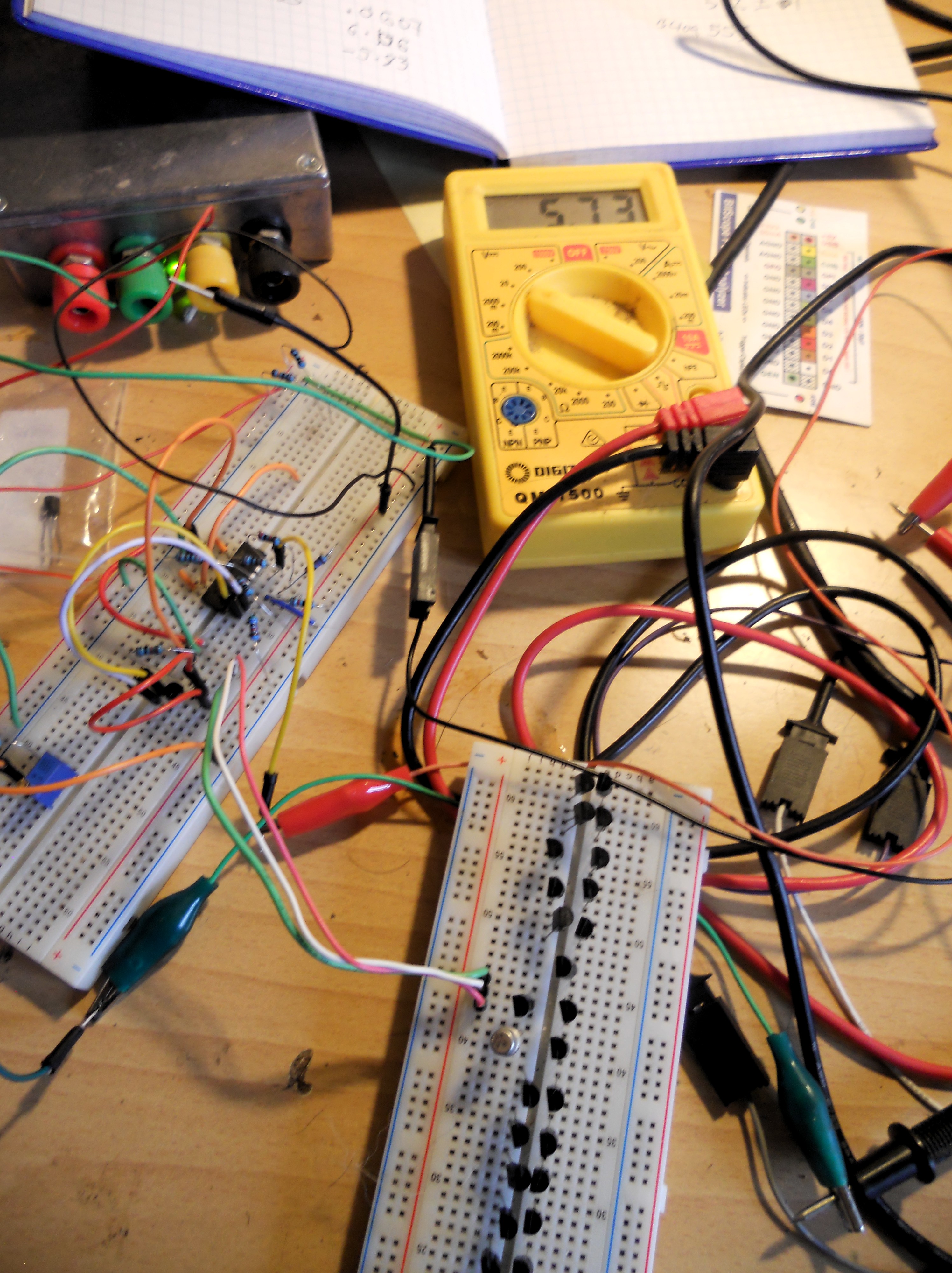
Moog refers to Vbe values of around 0.6V, and a target of matching within 2mV. I got similar values, 0.573 +/- 0.001V with only a couple of exceptions (even then less than 3mV difference). This seemed a little too good to be true, so I played around with things like changing the bias voltage, but still the values did seem surprising closely matched. Then a simple sanity check occurred to me. Putting a BC109 under test, this gave a value of 0.553V. Not matched to the 2N3904s.
So it looks like I got lucky 🙂
