Mostly pics for now, it took me ages to fit the new power supply & test, did have other things to do today…
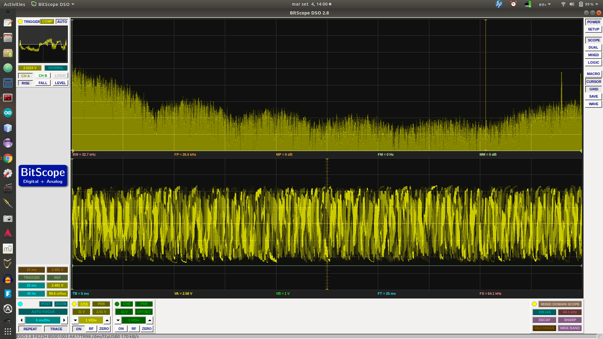
A 1 minute video of the testing
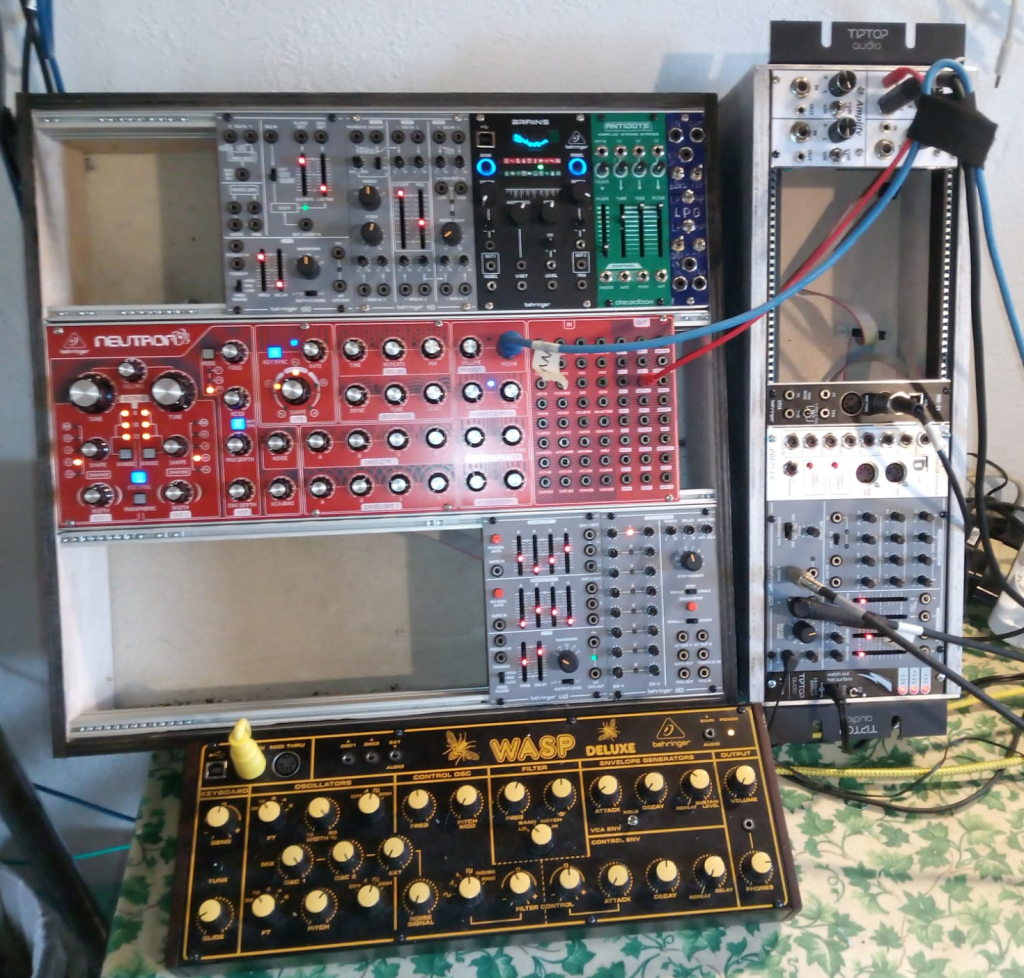
This is what the (mostly) analog (moderately) modular desk looks like now. Loads of lovely rack space!
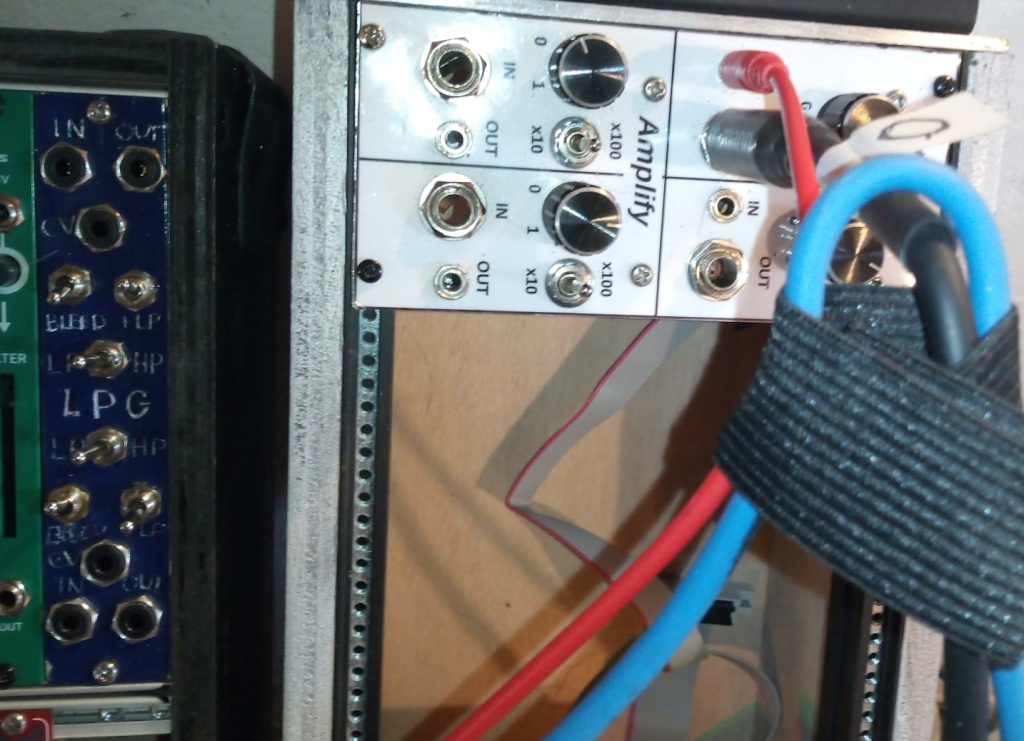
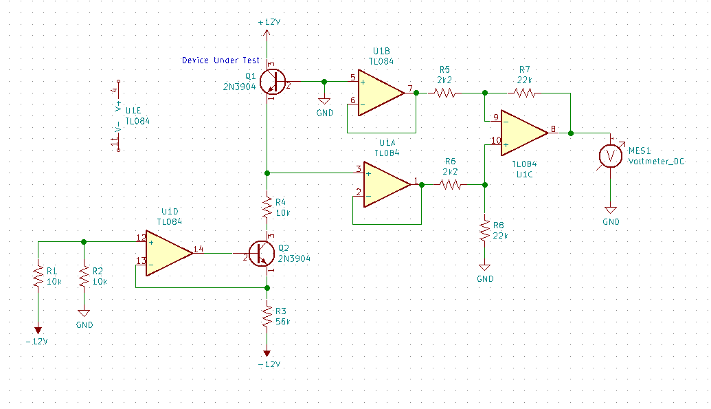
These two are modules I put together myself. First was the one on the right, two attenuators (a pot, I probably DC blocked so a couple of caps too) and two amplifiers (a couple of op amps each. I believe I used kcad for the schematic, should be around somewhere, but was pretty much datasheet stuff.
The one on the left, dual low pass gate, was very experimental. Vactrol-based, entirely passive. Surprisingly useful for very few components. The front panel was also a (failed) experiment.
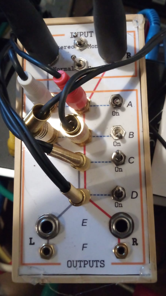
This is just a passive switch box I made to quickly change monitoring setup. Included here because the front panel technique is the one that has worked the best. Design on computer (I used LibreOffice Draw, it’s good for block diagrams etc). Do a rough printout to use as a template, cut/drill 3mm aluminium to match. Do a high quality printout on glossy paper. Laminate. Cut out and glue to the aluminium, cut out the holes with a scalpel.
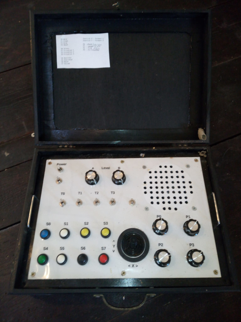
This is the Chatterbox, something I put together just before I started looking into modular. ESP32-based with decent 2-channel DAC, has MIDI in, and I even got WebSockets over Wifi going so it could be controlled from a web page. The ESP32 also has Bluetooth support, but I haven’t played with that yet).
Although I love the look, the case took way longer than I’d have liked to get together. Eurorack time!
It also revealed loads of little issues, eg. those push switches are hard work.
A bigger issue was that my code got messy. I’m not very experienced with C++ and the dual cores of the ESP32 did my head in a bit.
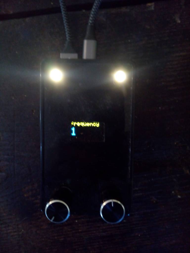
So next I made a version of another old idea, the Dreamachine. Like the Chatterbox this needed some controls and some DSP (for modulating the lights and generating white/pink noise for audio). My main aim was making a reasonably solid code framework. Instead of analogue pots I used rotary encoders and added a little display, only used the internal DACs.
I’ve got most of the coding done. The main frameworky idea was to have ESP32’s core 0 running all the UI code, core 1 doing the DSP. This seems to be working nicely, should be a good basis for other synthesis on the ESP32.
(The cable connects the device to an battery pack attached underneath).
I’ve got a bunch of analog and digital modules at various stages of design. More on those another day.


