I managed to kill my main blog this week, it might take me a little while to get going. For now I’ll just point the links on my home page here.
For any poor soul interested in how I got to this :
Early Rise and fall
I did blog very regularly, it looks like 2003-2013, at dannyayers.com, on a blogging engine I wrote. The Internet Archive seems to have captured most if not all of that, but I’m pretty sure I’ll have a (RDF) data dump around somewhere.But the real world interfered, my motivation (and finances) were tidal, usually ebbing. To mix metaphors, I lost that domain name for want of a nail. I subsequently blogged occasionally somewhere here on wordpress.com (I should have the data for that somewhere too).
He is risen!
But 3 or 4 years ago I got around to getting my own virtual server again. Took a while to get it together, I lost another couple of domain names along the way. I wasn’t really thinking about blogging at the time, it was more to host services for my HKMS project(s).
Then a year or two back a friend asked me to look at reviving an old WordPress plugin (SparqlPress). Because the idea was very (sem)webby, as well as a local install of WordPress it made sense to also have one live online. I had no future plans for it so just looked for the quickest way of getting it up and running. XAMPP seemed to fit the bill, a bundle of Apache + MariaDB (MySQL) + PHP + Perl. It was very easy to set up, WordPress on top took no time.
I used that while developing SparqlPress2. It only really covers the minimum requirements for modernising the original, but is far from being properly useful. The underlying idea, of exposing the WordPress data as Linked Data, is good for both the blogger and the Web at large. I do plan to have another look, I’m sure there’s a better way of doing the architecture, but I need to think of that first.
Then I thought, as I have this WordPress install, I might as well start using it for blogging.
…and down again
If all you want is to get WordPress up and running quickly, consider XAMPP. But if you think you might ever want to use any of its components for anything else, don’t. I’ve used Apache a good few times in the past, and even though it’s .conf setup is an absolute nightmare, it seemed to make sense to use it as the entry point on my host, pointing/proxying to my other services. Which would have been fine, but XAMPP deviates from the standard Apache setup. Its filesystem locations are different and even the way the dread .confs are organised is different. I was pretty certain that at some point I’d screw up.
So as of a few months ago I’d decided to swap XAMPP for a more standard install of the necessary components. A few days ago I noticed the blog was broken.
But I’ve got a lot of other things on my plate right now and it still doesn’t seem a high priority. If I get the urge to blog, I can do it here.
I’ve just started using ChatGPT 4 as a coding assistant. Even though I’m not yet used to creating optimal prompts, it’s been incredibly good. Much faster than my usual approach of googling for something similar to what I want and tweaking it, googling at every error…
So I think I’ll build another blog engine as part of HKMS, same basic approach as the other bits. The data lives in an online SPARQL store, browser JS using templating for building requests, formatting responses.
This mini-project is a tangent to the ELFQuake project proper, to help familiarize myself with machine learning techniques & tools.
Curwen/Kodaly Hand Signals
After this occurred to me last week, I’ve made some progress in implementation. But first some background.
Solfège Hand Signs
Solfège, Curwen, or Kodaly hands signs are a system of hand symbols representing the different pitches in a tonal scale. They’re used to provide a physical association of a pitch system to help connect inner hearing and reading of pitches with musical performance.
For the musically inclined among you, only having 7 tones may seem a bit limited – even Close Encounter’s tune uses the do at an octave. I believe Kodaly’s extension of Curwen’s system allows a greater range by holding the sign higher or lower (I think – need to google some more). Also the semitones in between are covered. The diagram above mentions fe, ta, and se, whatever they might be. But for now 7 tones feels like plenty.
The Aim
To build a system capable of recognizing Solfège hand signals and playing appropriate tones.
Right now I’m only thinking of getting to a proof of concept, though given that I’ve got an ESP32-Cam module sitting on my shelf, and TensorFlow Lite Micro is supported, there’s potential for embedded fun further down the line.
The Plan
Acquire a lot of images of the hand signals (with associated labels)
Train a machine learning system with that data
Use the trained model to take hand signal images from a webcam and generate the corresponding tones, in real time
Let me unwrap that, starting with 2.
MNIST
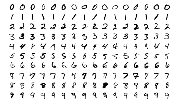
The MNIST database of handwritten digits is commonly used as a benchmark for testing pattern recognition/machine learning algorithms. It comprises a total of 70,000 images with associated labels (0-9), which looks something like this –
Typically you take the training set of 60,000 images, fire them (and their labels) at your learning system for as long as it takes. Then you use the test set of 10,000 images (and labels) to evaluate how good your system is at recognising previously unseen images.
This is isomorphic to the core of what is required to recognize hand signals.
There are a lot of systems coded up to work on MNIST. It’s hard not to see a competitive element where different algorithms are proposed that push the accuracy up a little bit further. Wikipedia lists a bunch of classifiers, with error rate ranging from 7.6% (Pairwise linear classifier) to 0.17% (Committee of 20 CNNS with Squeeze-and-Excitation Networks [?!]).
Where the code is available, it’s typically set up to allow reproduction of the results. You point say train.py at the MNIST image and label training set files, wait potentially a very long time, then point test.py at the test set files, then hopefully soon after some numbers pop out giving the accuracy etc.
While the MNIST database is ubiquitous, various limitations have been pointed out. The elephant in the room is that the fact that a particular system does exceedingly well on MNIST doesn’t mean it’ll be good for any other kind of images. This and other issues were the motivation for Fashion-MNIST, a database of more complex images.
I have absolutely no idea what kind of system topology will work well with the hand signals, they are qualitatively a lot different than handwritten digits. But, if I format my dataset as a drop-in replacement for MNIST, I can pick a wide variety of setups off the shelf and try them out, with no extra coding required (this is also the approach taken with Fashion-MNIST). Parameter tweaking will no doubt be needed, but simple trial & error should cover enough bases.
The MNIST format does look rather arcane, but it shouldn’t take me too long to figure a script to compose the data this way.
Back to the Plan part 1.
Data Acquisition
MNIST has 70,000 images. Even if I could capture one a second, this would still take about 20 hours. Noooo..!
But I’m only aiming for a proof of concept, I will consider that achieved with something like a 90% success rate. Almost ever paper you see featuring machine learning will have a chart somewhere with a curve that starts steep and quickly levels off, becoming virtually flat a little way below some desired goal.
I think it’s reasonable to assume most of the systems that can operate on MNIST-like data will have this characteristic, with size of training dataset on the horizontal axis and accuracy on the vertical.
How many sample images will be needed to get to 90%? Clearly it will depend on the algorithms, but in the general case I have no idea. Lots.
So I need to be able to capture images quickly.
After a bit of futile play trying to get a Python GUI app going I gave up (curse you Wayland!), decided to try Javascript in the browser instead. Which, after what experts might consider excessive time on StackOverflow and not enough on MDN API docs,
The capture of images from the webcam was straightforward via a <video> element (although there is an outstanding issue in that I couldn’t get the camera light to go off).
Processing, via <canvas> elements turned out to be a lot more convoluted than I expected, I didn’t find that intuitive at all. ‘hidden‘ is the keyword.
Similarly, it took me a good while to figure out a quick way of saving the final image to file (by addressing a hidden <a> element programmatically).
I started with mouse input on <button> elements but soon realised (as any fule kno) that for speed it had to be the keyboard. But that and the rest was pretty straightforward. Generating the tones was trivial, although my code might not be as considerate to the host as it could be.
A huge advantage of implementing this in a browser (aside from being able to get it to work) is the potential for crowdsourced data acquisition. I’ll tweet this!
It was pretty much an afterthought to try this on a mobile device. When I first tried it on my (Android) phone, Capture didn’t work. It is quite possible I had the camera open elsewhere, but I’m still confused why I could see the video stream. Today I showed it to Marinella on her phone, expecting Capture to fail there too. It worked! I just tried again on mine (making sure camera was off), it worked there too!
Even if it does basically work on mobile, there’s still a snag. Ok, from the desktop I can ask people to zip up a bunch of images and mail them to me or whatever. Doing things like that on a mobile device is a nightmare.
If anyone says their willing to capture a bunch of images, but it’ll have to be on mobile, I’m sure I can set something up to quickly post individual images from the application up to a server.
Onto Plan part 3.
Runtime Application
You make a hand signal to a camera, which is periodically taking snapshots. If a snapshot is recognised with reasonable certainty as being of a hand signal, the corresponding tone is played.
Implementation is very much To Be Decided, I’ve got all the data conversion & model play to do first.
Because the ML code will be built with Python, my original thought was to go with this for an application, like a little desktop GUI. I’ve since gone off this idea (blast your eyes, Wayland!). I sometimes forget that I’m a Web person.
So provisionally I’m thinking I’ll set it up as a service over HTTP. Aaron’s web.py is a fun thing I’ve not played with for a long time.
I nearly had kittens when danbri pointed this challenge out to me. I’ve thought for a long time earthquake prediction was well in scope for machine learning and have been dismayed at how little uptake there has been. (Surprised too, given the co-location of many tech people and the San Andreas fault…). Hopefully this competition will change things. Deadline is in 3 months, pretty significant $ prizes.
My second reaction was: “Great! I can work on ELFQuake and maybe win a prize!”. But that isn’t the whole picture. The competition is based around data generated in the lab, essentially by squashing a rock and recording its fractures. Apparently a reasonable approximation of geological effects.
I forget offhand where, but I’ve also seen a project aiming to use machine learning on real data. But that project, as with this competition, I feel is missing a trick. My gut says that although, sure, algorithms can almost certainly be useful in predicting seismic events, using the seismic data alone for training is a blinkered approach. These events, in the real world, occur as the result of the behaviour of a massively complex system. There are practical limitations on what can be modeled, but I’d suggest that it’s possible to creep a little further into the real world by bringing in data from other natural sources. For example, does the position of the moon influence the timing of events? Does seem at least credible, given that its gravity is enough to pull the oceans around.
The data source I reckon looks most promising is natural radio, signals that have been shown to sometimes contain artifacts associated with subsequent seismic events. This is the hypothesis of this project ELFQuake (ELF for Extremely Low Frequency, it’s in this frequency range and that of VLF, Very Low Frequency that earthquake precursors seem to occur).
For me, the Kaggle challenge has acted as a nudge, to get me moving on ELFQuake software again. What’s more, material has already appeared for the basic setup needed to process this data – data that has a lot in common with the ELFQuake targets. This is very convenient for me, as although I’m now getting somewhat familiar with the principles and algorithms of Deep Learning, my practical experience is virtually non-existent. So I’ve been given a great foot-up. Here’s some material using sklearn : video, github. The toolkit that seems to me the most appealing option is Keras on TensorFlow (on Anaconda), but a lot of the pre/post Python wrangling will be the same.
I’ve put my name down for the competition, it’s a bit of extra motivation – potential $$$s! – to work on this stuff, and also what I get together for it can be used as a placeholder in the end-to-end system I’m aiming for (seismic & radio sensors -> data acquisition -> [magic] -> Twitter notifications).
I’ve been a bit frustrated in recent weeks by electronic circuit design tools. The typical process is to draw out the circuit schematic, run simulations and then generate/draw PCB layouts etc. Many of the tools (especially on *nix) use SPICE format to represent the circuit topology between the different operations.
The tools I’ve looked at so far all appear to have one major flaw or another.
KiCad – the netlists it generates aren’t quite compatible with SPICE (circuit emulation) tools
Fritzing – the netlists it generate are nothing like SPICE format (I believe it uses XML)
So, the go-to representation as far as I’m concerned for pretty much anything is the Resource Description Framework (RDF). So I had a quick search around looking to see if anyone had looked at SPICE in RDF before. D’oh! I found a SPICE vocab I’d roughed out on GitHub around 2011. Jeez, my memory.
Since I did that post, JSON has become fairly ubiquitous, I’m sure it’s now most coders’ go-to representation of data. But in its basic form it isn’t Web-friendly, in the sense that it doesn’t natively support links.
Links could make things much easier to share and find: circuits, components, datasheets etc (the description of the circuit in RDF would include URLs for the components, which in turn could be associate with their characteristics, with their datasheets, etc etc).
There’s even a commercial angle. Given the list of components, a bill of materials can be generated. But typically nowadays you have to trawl through vendors to find suitable suppliers. But in RDF, the component could be associated with a vendor, with fields like the price etc. A distributed SPARQL query could figure much of this stuff out automatically.
Ok, why not use JSON? – There’s JSON-LD, which is an RDF representation, it’s JSON with links included.
One other idea. In the middle of typing this, I had a brief chat with Reto, told him what I was typing. He wondered whether there might be a role for inference (which is a good question, given the existence of RDF/OWL reasoners). Hmmm, my immediate response was, yeah, maybe something like consistency-checking a circuit for dangling wires. But Reto made the point that OWL probably wouldn’t be the best reasoning for the job, this might be more of a SHACL use case.
Off-topic. I needed to get my head into gear for work-work, and over the weekend I had an odd little idea I wanted to try. So here’s a quick & dirty write-up and video.
After playing with Arduino White Noise the other week, I did a bit of reading up on the Colors of Noise. Particularly interesting is Pink Noise, in which “each octave (halving/doubling in frequency) carries an equal amount of noise energy… This is in contrast with white noise which has equal intensity per frequency interval.”. It occurs a lot in nature, but is not entirely trivial to synthesize either using analog or digital processing. (Here’s a fairly accurate analog pink noise generator circuit).
Mind wandering, this led me onto chaotic signals. These are remarkably easy to slip into in the analog domain, essentially all you need is a non-linear system with feedback (and the right parameters) – see this old magazine write-up on non-linear circuits. They also easy to generate in the digital. The best known system is probably the Lorenz Attractor,
But there are much simpler discrete systems, notable the Logistic Map. This is just:
x1 = r * x0 * (1-x0)
where r is a constant, x0 is the current value of x, x1 the next value. With values of r between about 3.6 and 4, the thing goes chaotic.
This was pretty easy to plug into the same skeleton code I used for Arduino white noise generation. The result was the same distinctive kind of racket that the analog circuits generate. To provide a bit of control, I put a pot. on an analog input, scaling the read value between 0-1 and adding it to 3 to provide an interesting value range for r.
But what I wanted to play with wasn’t just this. One way of generating electronic (and mechanic) chaos is to drive an otherwise periodic system with a periodic signal, as in the chaotic double pendulum. But with pink noise on my mind, I was curious to see what would happen if a chaotic system was driven with white noise.
The code, again using the skeleton I already had, was straightforward. I added another pot. to another analog input to determine the level of the noise signal.
My code is a real hacky mess at the moment, mostly due to hopping between integer and float values, and scaling, but the core of it looks like this (effectively inside a loop):
  // Shift register-based random number generator (white noise)
  unsigned lsb = lfsr & 1;   /* Get LSB (i.e., the output bit). */
  lfsr >>= 1;                /* Shift register */
  lfsr ^= (-lsb) & 0xB400u;

  // control values
  noise_level = analogRead(NOISE_LEVEL_PIN); // will be 0 - 1023
  r_value = analogRead(R_VALUE_PIN);

  r = 3 + ((float)r_value) / 1024;

  noise_scale = ((float)noise_level) / 2048;

  x_scale = 1 - noise_scale;

  noise = noise_scale * ((float)lfsr) / 65536;

  x = x_scale * x + noise;

  // logistic map
  x = r * x * (1 - x);


  // the value to output
  temp3 = (uint16_t)(x * 65536); // scale & cast
I’m still learning about what can be done with Arduinos, the main target being data acquisition for the ELFQuake project (the material in this post is all about getting stuff out). But as it involves breadboarding, I’ve got another fun target in mind – a hybrid music synth.
I’ve been reading around what other people have done with the things. For analog output, especially when considering music synthesis, there’s a problem that needs solving.
(Note I’ve been playing with an Arduino Uno – some of the other models have improved features).
The Quality Issue
Unless you’re after bitcrushed, lo-fi, glitch sounds, you need a decent sample rate and resolution. For ballpark, CD audio has a 44.1kHz sample rate, offering something under 22kHz bandwidth, see Nyquist frequency. It’s 16-bit, which means in its basic form, it has a Signal/Noise Ratio of about 96dB – though there are tricks to improve this.
A typical digital synth would use a high sample rate through a dedicated Digital-to-Analog (DAC) chip, with associated circuitry to get things into the analog domain. But as they stand though, Arduinos are very much 8 bit-based. You can get 8 bit analog signals out of a digital output pin using Pulse Wave Modulation (PWM), followed by a very simple analog filter. The easiest way is analogWrite(pin, value). But then you pretty much immediately run into the sample rate problem – I can’t remember offhand, but it’s slow. But the Arduino has 3 built-in PWM timers which can be used to get a much better rate (into the 10s of kHz, so tolerable quality should be possible).
When using the interrupts, the code starts getting obfuscated, but the principle is the same as analogWrite().
(TCCRxx refers to control registers, OC1A (Arduino pin 9) and OC1B (Arduino pin 10). For more info check the ATmega328 Datasheet.)
For the resolution, it’s possible to combine the analog from more than one PWM output. There’s some excellent material on the Open Music Labs site about this, but the basic idea is to scale the (analog) values from the PWM outputs, so eg. one is 256x the other, corresponding to the low and high 8 bits of a 16 bit signal. My basic circuit looks like this:
However, it can pretty much be guaranteed it won’t be 16 bits coming out of here.
The Mozzi synth project uses the same kind of configuration, but they, more realistically, only aim for max 14 bits (and kinda amusingly, their example of a 14 bit output actually only receives 8 bit values, left-shifted 6 bits, and their circuit uses a 499k/3.9k ratio, specified at 0.5% tolerance…). More generally, I doubt very much if the actual output using the kind of circuit above will get anywhere close to 14 bits.
However (2), my gut feeling is that by paying a little more attention to the analog side, it will be possible to get something like 14+ bits. I plan to experiment on this, using a few little tricks:
send the digital outputs through voltage-referenced comparators, so they are as close to each other in ‘raw’ state as possible
buffer the voltage division
use considerably more sophisticated integration/filtering of the PWM (perhaps independently for each output)
Noise Generation
I must admit to have been gobsmacked to have seen some folks using wavetables to generate noise. The shift register-based generators only need a handful of very low-level processor operations, they should compile down to very fast machine code. Depending where the table is stored, I wouldn’t be surprised to find out the computation is faster than the lookup. On a memory-limited device like the Arduino, I’d say it’s worth the trade-off whatever.
To be continued…
Here’s the code (I’ve left in lines that refer to the ADC, might want to use a pot to control freq or level):
*snip*
oops – I forgot about all the << and >> in there, so rather than figuring out the markup escaping here, I’ve popped it on github.
Tidying up my desk a bit yesterday, I found a circuit on a breadboard I’d left hanging. Months ago I was looking into notch filters for removing mains hum, to clean up a ELF/VLF signal a wee bit. I’d put together a bootstrapped twin-T notch filter, but had got rather frustrated when testing it. I wanted to get a general idea of its response and (assuming it looked ok) tune it to 50Hz.
But I’ve only got a USB port Bitscope oscilloscope (the BS10 mixed-signal model) which does do basic frequency analysis and even has a signal generator built in. Unfortunately there’s no sweep for the sig gen, and the UI is so clunky I wound up making a little generator with an easily-twiddled knob. That still didn’t really give me what I was after in being able to clearly see what was going on.
Anyhow, today I thought I’d take another look. Got everything set up, did some manual sweeping which showed that the component values I’d used were quite a way out (more like 70Hz). But still no clear visualisation of the overall response.
Staring at the desk, pondering what to do next…there’s an Arduino Uno right in front of me. I’ve spent a fair while getting to know the things over the past few weeks. I’d noticed in passing that it had a tone() method, but hadn’t actually played with it. Ok, about 15 minutes later I had this loaded:
void setup (){
}

void loop() {
  int i;

  for (i = 35; i <= 100; i++) {
    tone(11, i);
    delay(10);
  }
}
A sweep generator!
Ok, its frequency range is limited and it gives a square wave out. So I took the output from pin 11 and fed that to a simple RC filter (15k, 220nF) which took the buzziness down a bit. Stray harmonics aren’t that much of an issue for the current problem, and 35-100 Hz cover the range I’m looking at.
One thing the Bitscope’s waveform generator allows is the fairly accurate setting of frequency. So I set that at 50Hz and put it in one scope input, the output of my notch filter into the other. After a bit of fiddling to get levels reasonably stable, I got this:
The yellow is my 50Hz reference, green the notch filter response. The harmonics on the ref are pretty dire – dunno, I guess it must be clipping. But look at that lovely notch in the green! Around 70 or so Hz, as measured before.
So this setup can help me quickly tune the notch down to where it’s needed. But that isn’t the real triumph here. What I wasn’t sure about is the rest of the response of the active notch. Where the passive notch goes from flat into a 6dB (I think) / octave drop into the notch, this version has noticeable mounds either side. Those are potentially very undesirable. If you look at the 50Hz marker here, my filter as it stands would boost that frequency. While I’m sure I can get the notch in a much better position than this, any drift (maybe due to environmental factors) could be very bad. So at the cost of less sharp notch, I reckon on balance the passive version is probably the one to go for.
PS.
A few hours on, and a bit more progress. I pulled out the active notch circuit, did calculations again and plugged in a passive one. Well, I say passive, am using a TL074 to buffer the signal.
The basic filter circuit is this:
Fc = 1/(2 pi R C)
Using C = 100nF (2C just two of them in parallel) and 33k for each of the two Rs on top, a single 15k for the R/2 I got something looking like a cleanish notch, centred on 47.8Hz. It took a little trial & error. The capacitors are just off-the shelf, ceramic I think, probably 10% tolerance but came from the same batch so should be reasonable well matched. 1% resistors, again off-the shelf, same batch.
I forgot to take a screenshot…
But as I measured previously, the ambient mains hum here also contains a significant amount of 3rd harmonic, ie. 150Hz. So I did the sums again for this.
Ran into a slight snag with my setup though – when sweeping up through a reasonable range for it to go over the 150Hz target, the spectrogram display was all over the place.
But, as an alternative to sweep, you can also test freq response with white noise (or an impulse, but that’s another story). Coincidentally I was playing with a pseudorandom number generator just yesterday (for DOG-1), so knew what to look for. I found one, to which I’ve made minor tweaks –
#define speakerPin 11

unsigned long lastClick;

void setup() {
  // put your setup code here, to run once:
   pinMode(speakerPin,OUTPUT);
   lastClick = micros();
}


/* initialize with any 32 bit non-zero  unsigned long value. */
#define LFSR_INIT  0xfeedfaceUL
/* Choose bits 32, 30, 26, 24 from  http://arduino.stackexchange.com/a/6725/6628
 *  or 32, 22, 2, 1 from
 *  http://www.xilinx.com/support/documentation/application_notes/xapp052.pdf
 *  or bits 32, 16, 3,2  or 0x80010006UL per http://users.ece.cmu.edu/~koopman/lfsr/index.html
 *  and http://users.ece.cmu.edu/~koopman/lfsr/32.dat.gz
 */
#define LFSR_MASK  ((unsigned long)( 1UL<<31 | 1UL <<15 | 1UL <<2 | 1UL <<1  )) unsigned int generateNoise(){    // See https://en.wikipedia.org/wiki/Linear_feedback_shift_register#Galois_LFSRs    static unsigned long int lfsr = LFSR_INIT;  /* 32 bit init, nonzero */    /* If the output bit is 1, apply toggle mask.                                     * The value has 1 at bits corresponding                                     * to taps, 0 elsewhere. */    if(lfsr & 1) { lfsr =  (lfsr >>1) ^ LFSR_MASK ; return(1);}
   else         { lfsr >>= 1;                      return(0);}
}


void loop() {
      /* ... */
      if ((micros() - lastClick) > 500 ) { // Changing this value changes the frequency.
        lastClick = micros();
        digitalWrite (speakerPin, generateNoise());
      }

}
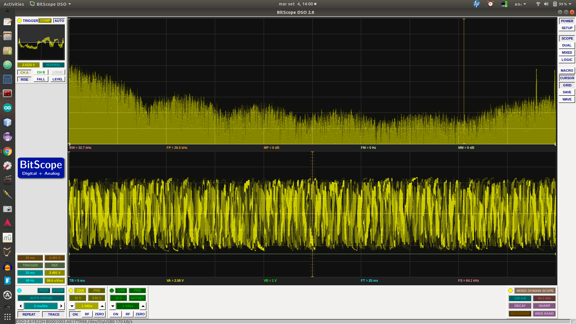
One tweak to use pin 11 as I’d already got that wired up. The other is rather sweet. The original code had a loop delay of 50 micros, related to the bandwidth. But that again wasn’t very clear on the spectrogram. Was nice white noise, but I’m only interested in the low end here. Making the micros 500, and letting the display accumulate for a minute, produced this:
There’s a nice notch pretty close to 50Hz, plus my new one, near enough at 150Hz (measured at 145Hz). The peak on the left is probably just an artifact of the setup – FFT does that sort of thing. Also the relative shallowness of the second notch I reckon is at least in part to the fact that it uses a linear scale on the spectrogram.
The values I used here were C = 47n, R = 22k, pleasingly standard values (the resistors gived those capacitors calculated at 22.57k, which was handy).
I’ve just got this set up on the breadboard around a TL074 quad op amp, using 3 op amps for unity gain buffers (each with a 1M to ground). Those things have input resistance of 10^12 ohms. So I’m now thinking I might just use one of them as the input stage for an ELV/VLF receiver. The 2N3819 input stage of the BBB-4 receiver I was going to try has a 10M resistor to ground, seems like plenty of leeway for that here. Input buffer, maybe give it variable gain of something like 1-100, to these filters (perhaps adding a little more gain along the way), then use the spare op amp to drive a couple of transistors for a small speaker/headphone level output.
Just trying it with a longish wire at the input, computer speakers at out, still way too much mains-derived noise to hear any natural signals, but the difference between the different stages of the circuit is really noticeable. I’ll have to get it soldered up, battery power, take it up the fields.
A little while ago I ordered a couple of Arduino Uno cards along with a couple of ESP8266 WiFi shields. It being my first hands-on with Arduinos, I was rather naive in my choice of shields. I got mine from banggood.com when they were listed as “ESP8266 ESP-12E UART WIFI Wireless Shield TTL Converter For Arduino UNO R3 Mega“, but while figuring out how to use them I found that various other budget tech vendors sell them. Their identifying feature is a charming little typo printed on the PCB :
Arduino ESP8266 WiFi Shiald Version 1.0 by WangTongze
The major problem is that the only official documentation is in Chinese (Mandarin?), something I haven’t a clue about. But by trawling the web and with a lot of trial and error I was eventually able to get code running on the card. I’ve written the process up spread across previous posts here, but it is rather convoluted, so for future ref. I’m pulling it together here. If you haven’t already bought one of these shields, you may well be better off getting something like a Wemos card.
Requirements
Arduino ESP8266 WiFi Shiald Version 1.0 by WangTongze
Computer with Arduino IDE loaded (I’m using a regular laptop with Ubuntu OS)
USB-TTL level serial converter – NB. I didn’t have one of these, but it turns out to be straightforward to use an Arduino Uno as a pass-through converter
USB cable, jumper leads (4 with a socket on one end)
Flashing Firmware
I must admit I don’t know if this step is entirely necessary, there may well be a quicker approach. But it worked for me, and is useful for resetting the card.
Using Arduino as USB-Serial Converter for the ‘Shiald’
The wiring is as follows :
Shiald Debug TX  => Uno Pin 1 (TX)
Shiald Debug RX  => Uno Pin 0 (RX)
Shiald Debug 5V  => Uno 5V
Shiald Debug GND => Uno GND
Uno Reset        => Uno GND

(Uno USB => Computer USB)
Flashing
Before connecting the Arduino to the computer, set the DIP switches on the Shiald as follows:
I had to tweak my paths a little bit, I forget the details, but whatever it took to get esptool.py running from the shell.
The script needed tweaking for the appropriate paths. Run:
ls /dev/tty*
– and the appropriate port should be obvious on the resulting list. My version of the script looks like this:
#!/bin/sh
# ESPToolDir="$HOME/Downloads/esptool"
FirmwareDir="$HOME/Arduino/ESP8266_NONOS_SDK"
cd "$FirmwareDir"
port=/dev/ttyACM0
if [ ! -c $port ]; then
 port=/dev/ttyACM1
fi
if [ ! -c $port ]; then
 echo "No device appears to be plugged in. Stopping."
fi
printf "Writing AT firmware in 3..."
sleep 1; printf "2..."
sleep 1; printf "1..."
sleep 1; echo "done."
echo "Erasing the flash first"
"esptool.py" --port $port erase_flash

"esptool.py" --chip esp8266 --port $port \
 write_flash -fm dio -ff 20m -fs detect \
 0x0000 "$FirmwareDir/bin/boot_v1.7.bin" \
 0x01000 "$FirmwareDir/bin/at/512+512/user1.1024.new.2.bin" \
 0x3fc000 "$FirmwareDir/bin/esp_init_data_default_v08.bin" \
 0x7e000 "$FirmwareDir/bin/blank.bin" \
 0x3fe000 "$FirmwareDir/bin/blank.bin"

echo "Done."
The messages given by esptool.py are pleasingly informative, but I found I have to press the reset button on the Shiald when the message got to:
...
Hard resetting...
esptool.py v2.2.1
Connecting...
The original script suggested using miniterm to check this had worked. I used the Arduino IDE. First unplug the USB and set the DIP switchesto all Off.
After plugging back in again & launching the IDE, go to Tools -> Port and choose whatever looks right. Under Tools -> Board choose NodeMCU 1.0 (ESP 12E module). Then go to Tools -> Serial Monitor.
In the serial monitor, set the baud rate to 112500 and then click reset on the Shiald.
You should get a message that ends in ‘ok‘.
At this point you should be able to communicate with the Shiald using AT commands. Two useful things:
AT+UART_DEF=9600,8,1,0,0
This will flip the baud rate down to 9600.
AT+GMR
Gives the versions of various things.
At this point it should be possible to upload software to the Shiald (with the DIP switches Off, Off, On, On) from the Arduino IDE.
Tools -> Board NodeMCU 1.0 (ESP12)
I’ve found that it often takes several attempts (and hits of the reset switch) to get a successful upload, no matter what the baud rate.
e.g. this minimal web server:
#include <ESP8266WiFi.h>
#include <WiFiClient.h>
#include <ESP8266WebServer.h>
const char* ssid = "AllPay Danny";
const char* password = "not this";
ESP8266WebServer server(80); // HTTP server on port 80

IPAddress ip(192, 168, 0, 14); // where xx is the desired IP Address
IPAddress gateway(192, 168, 0, 1); // set gateway to match your network
IPAddress subnet(255, 255, 255, 0); // set subnet mask to match your network

void setup() {
 Serial.begin(9600);
 WiFi.disconnect(); // Disconnect AP

 WiFi.config(ip, gateway, subnet);

 WiFi.mode(WIFI_STA);
 WiFi.begin(ssid, password); // Connect to WIFI network
// Wait for connection
 while (WiFi.status() != WL_CONNECTED) {
 delay(500);
 Serial.println(".");
 }
 Serial.print("Connected to ");
 Serial.println(ssid);
 Serial.print("IP address: ");
 Serial.println(WiFi.localIP());
server.on("/", [](){
 server.send(200, "text/plain", "Hello World");
 });
server.begin(); // Start HTTP server
 Serial.println("HTTP server started.");
}
void loop() {
 server.handleClient();
}
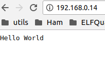
Pointing a browser at the chosen IP address should now work.
There’s a complication to comms between the Arduino and the Shiald. It seems the serial Tx/Rx lines of the ESP8266 connect to ports 1 & 2 on the Shiald – the Arduino’s Tx/Rx.
Again, I’m not really sure how essential this is, but it certainly works to wire other ports on the Arduino to the serial on the Shiald and use the SoftwareSerial lib. For reliability a baud rate of 9600 seems advisible.
Remember before uploading to remove the jumpers and change the board settings in the Arduino IDE.
At runtime, the following wiring worked for me:
Arduino   | Shiald

GND       - Debug GND
+5v       - Debug 5v
Digital 2 - Digital 0
Digital 3 - Digital 1
For my own application I want to be able to read values from the Analog Ins of the Arduino (6) and ESP8266 (1) and expose these (and one or two other little things) on a web server over Wifi. I’ve made a bit more progress towards this, will upload code to this project’s GitHub repo once I’ve tweaked to hide passwords.
So…this is my current setup:
The lower part is a Shiald piggybacking an Arduino Uno, the upper another Arduino acting as a serial interface direct to the Shiald. Each Arduino is going to a USB port on the laptop.
The wiring – the Shiald has its pins 1 & 2 bent out of line and connected instead via jumpers to pins 2 & 3 on the host Arduino. The Arduino acting as a serial interface has is as above, less the power lines.
For writing code to the Shiald, the DIP switches are at Off, Off, On, On. At runtime they’re at On, On, Off, Off.
I’m still using the Arduino IDE, flipping between USB port and board (Arduino Uno/NodeMCU 1.0).
It’s a bit of a pain flipping between the configs, but takes less time than uploading a reasonably long program to the Shiald, so I can’t really complain.
I’m really tired, but while trying to watch TV got to thinking about the Wifi board I’ve been playing with (described in previous post). I’d got as far as loading firmware that allowed it to speak AT codes. Couldn’t resist having a quick look at what could be done next. Luckily I went to my bookmarks first rather than looking at my notes here, because there was a page I must have bookmarked early on and forgotten about : Arduino UNO + ESP8266 ESP-12E UART WIFI Shield. It contains code for a minimal web server.
Looking at an image in this post reveals that the Shield there is there very same Shiald [sic] I have. Only problem, the author uses a USB-serial adapter to talk to it, something I don’t have. But wait – I found a way of rigging the Arduino to act as such an adapter (previous post).
I saw somewhere, and confirmed (by using a tablet to scan for WiFi networks) that the default IP address for the Shiald is rather an obscure one, off my local subnet anyway. But a bit of googling gave me the info necessary to set the IP to something else.
After fiddling a bit with the baud rate, a little blue light started flashing next to the ESP8266 chip, and it worked!
In the IDE:
In the Serial console:
And in a browser! Woo-hoo!
Here’s my tweaked version of the script:
#include <ESP8266WiFi.h>
#include <WiFiClient.h>
#include <ESP8266WebServer.h>
const char* ssid = "AllPay Danny";
const char* password = "not this";
ESP8266WebServer server(80); // HTTP server on port 80

IPAddress ip(192, 168, 0, 14); // where xx is the desired IP Address
IPAddress gateway(192, 168, 0, 1); // set gateway to match your network
IPAddress subnet(255, 255, 255, 0); // set subnet mask to match your network

void setup() {
 Serial.begin(115200);
 WiFi.disconnect(); // Disconnect AP

 WiFi.config(ip, gateway, subnet);

 WiFi.mode(WIFI_STA);
 WiFi.begin(ssid, password); // Connect to WIFI network
// Wait for connection
 while (WiFi.status() != WL_CONNECTED) {
 delay(500);
 Serial.println(".");
 }
 Serial.print("Connected to ");
 Serial.println(ssid);
 Serial.print("IP address: ");
 Serial.println(WiFi.localIP());
server.on("/", [](){
 server.send(200, "text/plain", "Hello World");
 });
server.begin(); // Start HTTP server
 Serial.println("HTTP server started.");
}
void loop() {
 server.handleClient();
}
The blog post goes on to Part 2 Upload code to Arduino, which I’ll try next – when I’m properly rested 🙂
PS.
Just tried this Part 2 bit, essentially comms between Shiald & Arduino. It nearly worked :
Data received: . .
Conoected to AllPay Danoy
IP address: 092.168.0.04C!⸮⸮⸮⸮ٕɁ⸮⸮
I’ve read somewhere that the Software Serial struggles at high baud rates, and this example is using 115200 so presumably that’s the problem. Bit of tweaking required.
PPS.
I flipped the baud rate in the code based on that in the blog post to 9600, and with the Arduino as serial converter uploaded the new code to the Shiald (at 115200 baud), set as NodeMCU 1.0. Uploading took a good few attempts, but finally it worked.
I also changed the Arduino part of the code to use different ports :
Arduino   | Shiald

GND       - Debug GND
+5v       - Debug 5v
Digital 2 - Digital 0
Digital 3 - Digital 1
The switches on the Shiald are at (1,2,3,4) On, On, Off, Off.
And finally, the Hello World is still visible on the IP address I set. And what’s more, in the serial monitor (now set to 9600 baud) I see:
Connected to AllPay Danny
IP address: 192.168.0.14
HTTP server started.
Yay! It all works.
So…
Next
First thing I should do is pull together all the various bits from the last post and this, with relevant material from linked pages, and write it up as a from scratch to here procedure. I won’t remember, and also anyone that buys the same boards will stand a chance of getting things going.
Then I need to think about what I’m going to do on the analog/sensor side. What I can do with the hardware I’ve got is fairly limited – a key factor being the speed of the data acquisition on the Arduino. But I should have the necessary for me to build something that operates end-to-end with essentially the same topology as my target design.
Regarding code on the Arduino & Shiald, the next steps will be to :
Get the data from the single Analog Input on the Shiald, buffer/filter it and expose it on a local web server. With a little analog pre-amp & filter this should be enough for a single-channel seismometer.
Do the code necessary on a regular computer to access and do something with the data from the web server on the Shiald.
Get the data from the 6 Analog Inputs on the Arduino, buffer/filter it, transfer it to the Shiald and again expose on a local web server. I might well try the analog bandpass filter idea mentioned in my previous post.
As 2. but for the 6 channels.
A global job to put together in parallel with the above is the code necessary for self-description of the units to provide status information alongside the data. RDF and Web of Things time!
So now I’ve got fairly fun jobs to get on with on every side of this project :
Sensor hardware
Arduino/Shiald software
Comms/post-processing software – I can get on with the Deep Learning bits using online sources, haven’t looked at that for weeks
Notification system – hook the Deep Learning bit output to Twitter
On the hardware side of this project, I want to capture local seismic and ELF/VLF radio data. I’ve given myself two major constraints: it should be simple; it should be low cost. These constraints are somewhat conflicting. For example, on the seismic side, a simple approach would be to purchase a Raspberry Shake, an off-the-shelf device based on a Raspberry Pi and an (off-the-shelf) geophone. Unfortunately, these gadgets start at $375 USD, and that’s only for one dimension (and there may be software licensing issues). I want to capture 3D data, and want to keep the price comfortably under $100. Note that project non-constraints are absolute measurement, calibration etc. So the plan is to hack something. I’m taking rather a scattergun approach to the hardware – find as many approaches as are feasible and try them out.
Both the seismic and radio sensor subsystems have particular requirements when it comes to physical location. The seismic part should ideally be firmly attached to local bedrock; the radio part should be as far away as possible from interference – mains hum being the elephantine wasp in the room. For my own installation this will probably mean bolting the seismic part to my basement floor (which is largely on bedrock) and having the radio part as far up the fields as I can get it.
What seems the most straightforward starting point is to feed data from the sensors into a local ADC, pass this through a microcontroller into a WiFi transceiver, then pick this up on the home network. (WiFi range may well be an issue – but I’ll cross that bridge when I come to it).
The two microcontroller systems that seem most in the frame due to their relatively low cost are the aforementioned Raspberry Pi and the Arduino family. For a first pass, something Arduino-based seems the best bet – they are a lot cheaper than the Pis, and have the advantage of having multiple ADCs built in (compared to the Pi’s none – though there are straightforward add-ons).
Arduino Fun
Quite a while ago I ordered a couple of Arduino Unos and WiFi shields from Banggood, a China-based retailer of low cost stuff. My only prior experience with Arduinos was when my brother was building something MIDI-related and hit a code problem. He mailed me on the offchance and amusingly I was able to solve the problem in my reply – it was a fairly easy bit of C (I hadn’t done any other C for years, but coding is coding).
I instantly fell in love with the Arduino boards (actually a clone by GeekCreit). After very little time at all I was able to use the Arduino IDE to get some of the example code running on one of the devices. Light goes on, light goes off, light goes on… Very user friendly.
ESP8266 Nightmares
In my naivety, I assumed the WiFi shields would be as straightforward. Most probably are, but the ones I ordered have been distinctly painful so far. But I can at least put slow progress so far down as a learning experience. Essentially the ones I got have several issues. The story so far:
The first of these posts describes a nifty little setup, using an Arduino board as a converter from USB to TTL level RS232 that the Shiald can understand (I didn’t think to order such an adapter). It looks like this:
By default the Shiald plugs its serial TX/RX pins to the Arduino’s, which does seem a design flaw. But this can (apparently) be flipped to using software serial via regular digital I/O pins on the Uno. A key thing needed is to tell the Shiald to use 9600 baud rather than its default 115200. The setup above allows this. This part worked for me.
However, at this point, after bending the TX/RX pins out of the way on the Shiald and plugging it in on top of the Uno (with jumpers to GPIO for TX/RX), I couldn’t talk to it. So going back to Claus’s post, he suggests updating the Shiald’s firmware. Following his links, I tried a couple, ended up with the setup spewing gibberish (at any baud rate).
At this point – after a good few hours yesterday, I was ready to cut my losses with the WiFi Shialds. I’d mentioned to danbri that I was struggling with these cards and he mentioned that he’d had the recommendation (from Libby) of Wemos cards. So I started having a look around at what they were. As it happens, they have a page on their wiki Tutorial – Returning a Wemos D1 Mini to Factory Firmware (AT). The D1 uses the same ESP8266 chips as my Shiald, so this morning, nothing to lose, adjusted the script and gave it a shot. Going back to the setup in the pic (with DIP switches tweaked as Claus suggests) it worked! (Tip – along the way of flashing, I had to press the Shiald’s reset button a couple of times).
So far so pleasing – I thought I might have bricked the board.
After this I’d tried with the Shiald mounted on top of the Arduino in a good few configurations with various different software utilities, haven’t yet got everything talking to everything else, but this does feel like progress.
Issues Raised and a Cunning Plan
Sooo… these Shialds have been rather thieves of time, but it’s all learning, innit.
These bits of play have forced me into reading up on the Arduinos a bit more. For this project, a key factor is the ADC sample rate. It seems that the maximum achievable for a single ADC is around 9kHz (with 10 bit precision). That should be plenty for the seismic sensor. The radio sensor is another matter. I’d like to be able to cover up to say 20kHz, which means a sampling rate of at least 40kHz. I’m still thinking about this one, but one option would be to use an ADC shield – these ones from Mayhew Labs look plenty – though getting the fast data along to WiFi could well be an issue (intermediate baud rates). If necessary, some local processing could be a workaround. I have been intending to present the radio data to the neural network(s) as spectrograms so maybe eg. running an FFT on the Arduino may be feasible.
Along similar lines, I may have a Cunning Plan, that is to shift some of the processing from digital to analog. This is likely to need a fair amount of research & experimentation, but the practical circuitry could be very straightforward. It seems at least plausible that the earthquake precursors are going to occur largely in particular frequency regions. The Arduino has 6 analog inputs. So imagine the radio receiver being followed by 6 bandpass filters, each tuned around where precursors may be expected. A simple diode & (leaky) capacitor peak level detector for each of these could provide a very crude spectrogram, at a rate the Arduino could easily handle. Op amp BP filters are straightforward and cheap, so an extra $5 on the analog side might save $40 and a oad more work afterward.
Regarding the research – a key source is (of course) Renato Romero’s vlf.it, notably the OPERA project – although that does seem to focus at the low end of potential frequencies.