Happy New Year!

A good time to take stock, huddled in front of the fire.

Boo!

As is often the case, I’ve been moving more slowly on this project than I’d have liked. Lack of resources is a continuing problem, but my own tendency to procrastinate has been by far the biggest obstacle to progress. On top of this, my main dev computer packed up recently, so until I can get that fixed or replaced I’m getting things set up again on an old laptop. Frustrating.

Three Steps Forward…

My strategy of taking a multi-pronged approach has had its pros and cons. I’ve got a prototype VLF receiver mostly built and have spent quite a lot of time playing around with Arduinos and related devices. On the software side – which is really the novel aspect of this project – I did make reasonable progress, getting together a provisional system design and some of the implementation. But then stalled. My desire to build hardware to allow local data collection has been something of a distraction, when there’s nothing stopping me from working with data from INGV and VLF.it.

Plans.

Looking ahead, I really need to reboot myself on the software dev. The ultimate target for running code will be nothing more sophisticated than this laptop. But for exploring algorithms and probably NN training, pre-optimisation, I reckon using cloud services will be my best bet. Concurrently I can look at some of the side prongs that I want to include in the system as a whole – notably web publication of data and automatic generation of Twitter notifications.

As everyone that’s worked on a solo project knows, I’ve also got a lot more material in my head or at best sketched in notebooks that needs writing up. How often has the New Year Resolution been : “Write more docs.”.

Mini-Seismograph

On the hardware side, until I’ve got my income a bit better sorted out I am pretty much limited to rather a scattergun approach using what ever components I have at hand. As well as finishing off the mostly-built VLF receiver, I’ve also got the bits for a basic seismograph. It’ll essentially be :

  •  ESP32microcontroller + comms :  core of the subsystem, handling the acquisition and preprocessing of data, which it will expose using a basic web server, accessible from the local network (the ESP32 includes WiFi connectivity).
  • MPU6050sensors : accelerometer +gyroscope : a tiny MEMS device, connected over I2C.
  • MicroSD carddata logging : experience shows that 100% connectivity is implausible, so some local history is very desirable
  • Tiny RTC cardrealtime clock :  the comms will be async, so accurate local timestamps are a must.

The ESP32 is a remarkably capable little device and I’m reasonably confident of the viability of interfacing the peripherals. Hopefully just a matter of plodding through example code for each, tweaking as needed.

The MPU6050 sensors are much less sensitive than those of typical seismometers. Only events with significant magnitude are likely to be detectable. It remains to be seen, but I have my suspicions that having 2 different types of sensor in there mean it will, with a bit of wrangling, be possible to get more effective sensitivity than the individual sensor data would yield. Whatever, once the wiring and code is in place for this setup, it should be trivial to extend it to use a more sensitive sensor. (Note the Raspberry Shake 4D configuration.)

Also…

I’ve got a little tangential project on the go. ELFQuake is in essence about trying to model aspects of a physical system : Earth geology and its electronically-detectable artifacts. Creating an analogue in software that captures enough to be able to make useful predictions. Also I’m increasingly convinced that the design of analog circuits between the sensors and standard data acquisition elements (ADCs etc) will have a major impact on the potential success of the system. Putting these points together, it shouldn’t seem that off the wall that I’ve been working on the design of an analog computer. (I must admit I also want to play with chaotic systems, this is something I’ve been messing about with for years).


Matching Transistors for Log/Exp Converters

Slightly off-topic again.

I’ve been looking at analog log/exp converters, primarily with music synth applications in mind. Here’s a typical Voltage Controlled Oscillator circuit, which uses a pair of transistors as part of the exponential conversion sub-circuit.  But there may well be potential for using an analog log converter to effectively improve the resolution of the ADC part of a seismic data acquisition system. Note that earthquake magnitude measurements are usually expressed as log values – e.g. in the Richter Scale, a magnitude 5 event has an amplitude 10x that of a magnitude 4 event.

There’s a useful selection of general-purpose log & exp converters in TI Application Note AN-30. When building such circuits from op amps + transistors, there are two factors that can significantly affect accuracy. The first is the effect of temperature on transistor characteristics. This is usually offset by using a temperature-sensitive (‘tempco‘) resistor. I don’t currently have any of these… The second issue is that the circuits generally involve a pair of transistors in a balanced configuration. Here it’s useful to select transistor with closely matched characteristics.

Screenshot from 2018-08-14 19-01-37

The classic circuit for testing for matching was given by none other than Dr. Robert Moog:

Screenshot from 2018-08-14 19-02-59

More sophisticated variations are described at Music from Outer Space. I’ve got a bag of 100 2N3904 transistors (about €2 from China), so I decided to have a go at finding some matched pairs.

My circuit began with a silly mistake. I’d misread Moog’s circuit, thinking that both test points were floating, not noticing that one was ground. I only realised once I’d got the thing breadboarded. No big deal, and buffering both lines did offer a bit more scope for experimentation. This is what I ended up with:

Screenshot from 2018-08-14 17-56-28

I used KiCAD for the diagram, files are on github.

The left-hand side is the same as Moog’s, just with a better op amp and 1% resistors. The right-hand side is a basic instrumentation amplifier consisting of a couple of unity-gain buffers feeding a differential amplifier with gain of 10. I initially tried a gain of 100 (using 220k rather than 22k around U1C), with a bias voltage (from a pot) on pin 5 of U1B, but this turned out to be over-sensitive, it was too easy to flip the output to one rail of the other.

I didn’t see much point in accurate reference voltages as in the MFOS designs, my 12v is regulated and after I’d left everything connected for a little while, there was too much variation in individual measurements.

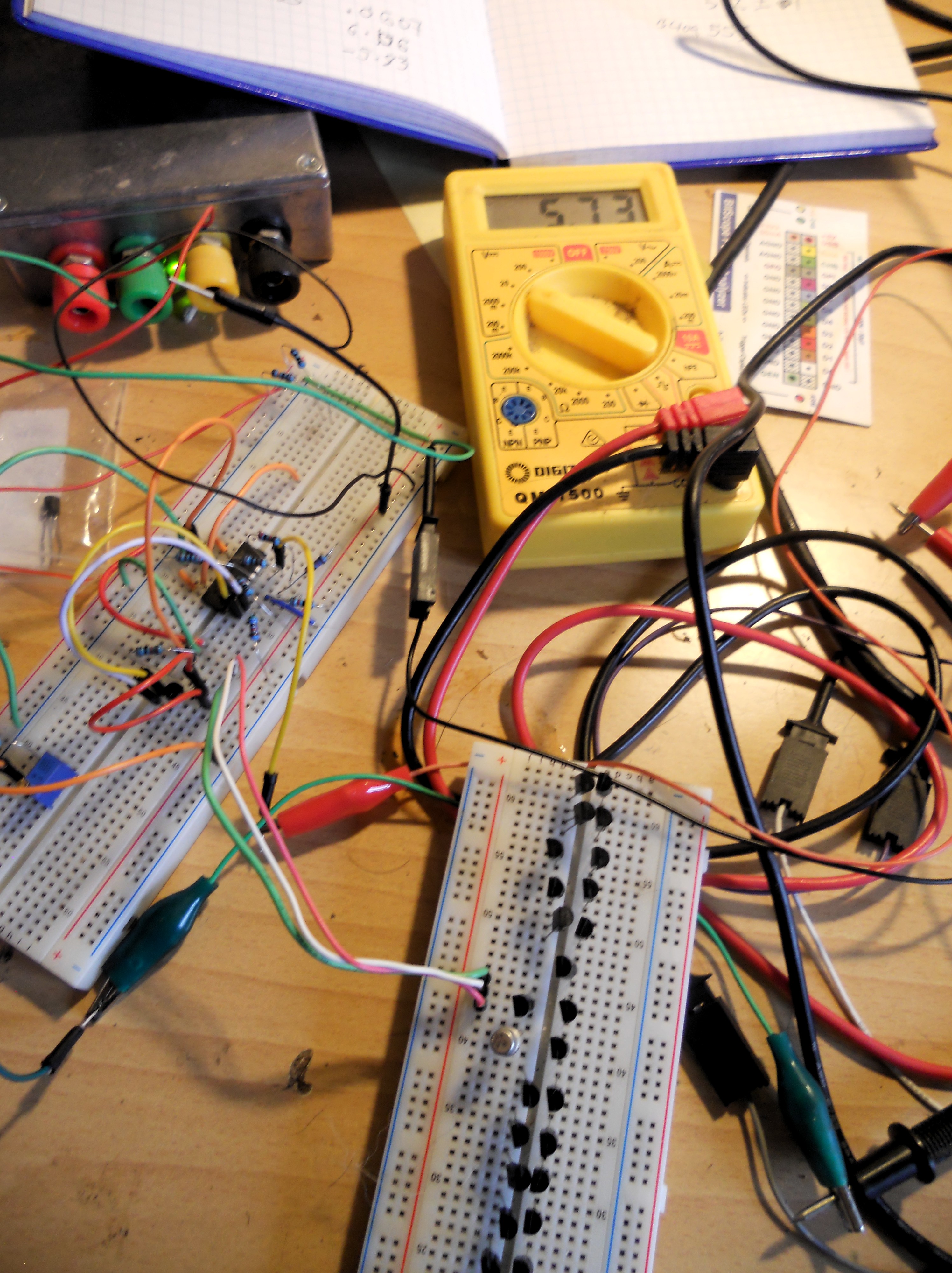
To do mass comparisons while avoiding touching the transistors (and warming them up), I stuck 40 of them into a breadboard:

DSCN1955.JPG

Moog refers to Vbe values of around 0.6V, and a target of matching within 2mV. I got similar values, 0.573 +/- 0.001V with only a couple of exceptions (even then less than 3mV difference). This seemed a little too good to be true, so I played around with things like changing the bias voltage, but still the values did seem surprising closely matched. Then a simple sanity check occurred to me. Putting a BC109 under test, this gave a value of 0.553V. Not matched to the 2N3904s.

So it looks like I got lucky 🙂


Arduino – initial experiences

skip to Arduino/WiFi bit, also Issues Raised and a Cunning Plan

Requirements & Constraints

On the hardware side of this project, I want to capture local seismic and ELF/VLF radio data. I’ve given myself two major constraints: it should be simple; it should be low cost. These constraints are somewhat conflicting. For example, on the seismic side, a simple approach would be to purchase a Raspberry Shake, an off-the-shelf device based on a Raspberry Pi and an (off-the-shelf) geophone. Unfortunately, these gadgets start at $375 USD, and that’s only for one dimension (and there may be software licensing issues). I want to capture 3D data, and want to keep the price comfortably under $100. Note that project non-constraints are absolute measurement, calibration etc. So the plan is to hack something. I’m taking rather a scattergun approach to the hardware – find as many approaches as are feasible and try them out.

Both the seismic and radio sensor subsystems have particular requirements when it comes to physical location. The seismic part should ideally be firmly attached to local bedrock; the radio part should be as far away as possible from interference – mains hum being the elephantine wasp in the room. For my own installation this will probably mean bolting the seismic part to my basement floor (which is largely on bedrock) and having the radio part as far up the fields as I can get it.

What seems the most straightforward starting point is to feed data from the sensors into a local ADC, pass this through a microcontroller into a WiFi transceiver, then pick this up on the home network. (WiFi range may well be an issue – but I’ll cross that bridge when I come to it).

The two microcontroller systems that seem most in the frame due to their relatively low cost are the aforementioned Raspberry Pi and the Arduino family. For a first pass, something Arduino-based seems the best bet – they are a lot cheaper than the Pis, and have the advantage of having multiple ADCs built in (compared to the Pi’s none – though there are straightforward add-ons).

Arduino Fun

Quite a while ago I ordered a couple of Arduino Unos and WiFi shields from Banggood, a China-based retailer of low cost stuff. My only prior experience with Arduinos was when my brother was building something MIDI-related and hit a code problem. He mailed me on the offchance and amusingly I was able to solve the problem in my reply – it was a fairly easy bit of C (I hadn’t done any other C for years, but coding is coding).

I instantly fell in love with the Arduino boards (actually a clone by GeekCreit). After very little time at all I was able to use the Arduino IDE to get some of the example code running on one of the devices. Light goes on, light goes off, light goes on… Very user friendly.

ESP8266 Nightmares

In my naivety, I assumed the WiFi shields would be as straightforward. Most probably are, but the ones I ordered have been distinctly painful so far. But I can at least put slow progress so far down as a learning experience. Essentially the ones I got have several issues. The story so far:

The boards I got are labeled “Arduino ESP8266 WiFi Shiald Version 1.0 by WangTongze”. Yup, that’s ‘Shiald’, not auspicious. The first major issue was that the only official documentation was in Chinese (mandarin?). I wasted a lot of time trying to treat them as more standard boards. But then found two extremely helpful blog posts by Claus : Using ESP8266 Shield ESP-12E (elecshop.ml) by WangTongze with an Arduino Uno and Arduino ESP8266 WiFi Shield (elecshop.ml) by WangTongze Comparison.

The first of these posts describes a nifty little setup, using an Arduino board as a converter from USB to TTL level RS232 that the Shiald can understand (I didn’t think to order such an adapter). It looks like this:

arduino1

By default the Shiald plugs its serial TX/RX pins to the Arduino’s, which does seem a design flaw. But this can (apparently) be flipped to using software serial via regular digital I/O pins on the Uno. A key thing needed is to tell the Shiald to use 9600 baud rather than its default 115200. The setup above allows this. This part worked for me.

However, at this point, after bending the TX/RX pins out of the way on the Shiald and plugging it in on top of the Uno (with jumpers to GPIO for TX/RX), I couldn’t talk to it. So going back to Claus’s post, he suggests updating the Shiald’s firmware. Following his links, I tried a couple, ended up with the setup spewing gibberish (at any baud rate).

At this point – after a good few hours yesterday, I was ready to cut my losses with the WiFi Shialds. I’d mentioned to danbri that I was struggling with these cards and he mentioned that he’d had the recommendation (from Libby) of Wemos cards. So I started having a look around at what they were. As it happens, they have a page on their wiki Tutorial – Returning a Wemos D1 Mini to Factory Firmware (AT). The D1 uses the same ESP8266 chips as my Shiald, so this morning, nothing to lose, adjusted the script and gave it a shot. Going back to the setup in the pic (with DIP switches tweaked as Claus suggests) it worked! (Tip – along the way of flashing, I had to press the Shiald’s reset button a couple of times).

arduino-at

So far so pleasing – I thought I might have bricked the board.

(See also ESP8266 Wifi With Arduino Uno and Nano)

After this I’d tried with the Shiald mounted on top of the Arduino in a good few configurations with various different software utilities, haven’t yet got everything talking to everything else, but this does feel like progress.

Issues Raised and a Cunning Plan

Sooo… these Shialds have been rather thieves of time, but it’s all learning, innit.

These bits of play have forced me into reading up on the Arduinos a bit more. For this project, a key factor is the ADC sample rate. It seems that the maximum achievable for a single ADC is around 9kHz (with 10 bit precision). That should be plenty for the seismic sensor. The radio sensor is another matter. I’d like to be able to cover up to say 20kHz, which means a sampling rate of at least 40kHz. I’m still thinking about this one, but one option would be to use an ADC shield – these ones from Mayhew Labs look plenty – though getting the fast data along to WiFi could well be an issue (intermediate baud rates). If necessary, some local processing could be a workaround. I have been intending to present the radio data to the neural network(s) as spectrograms so maybe eg. running an FFT on the Arduino may be feasible.

Along similar lines, I may have a Cunning Plan, that is to shift some of the processing from digital to analog. This is likely to need a fair amount of research & experimentation, but the practical circuitry could be very straightforward. It seems at least plausible that the earthquake precursors are going to occur largely in particular frequency regions. The Arduino has 6 analog inputs. So imagine the radio receiver being followed by 6 bandpass filters, each tuned around where precursors may be expected. A simple diode & (leaky) capacitor peak level detector for each of these could provide a very crude spectrogram, at a rate the Arduino could easily handle. Op amp BP filters are straightforward and cheap, so an extra $5 on the analog side might save $40 and a oad more work afterward.

Regarding the research – a key source is (of course) Renato Romero’s vlf.it, notably the OPERA project – although that does seem to focus at the low end of potential frequencies.

Hall Effect-based Seismometer, Sanity Check Experiments

PS. Oops! I made a silly mistake in the breadboarding, if you look closely at the photo you can see that the 10k ground resistor at the input of the op amp is going to + input, not – as intended. Which kind of messes up all my measurements. Hey ho. I have since made a ball-bearing in a jar (1 axis) sensor and roughed out a signal conditioning circuit (which will now need tweaking…), so will repeat the experiment here and do another post asap.

A fun part of this project is the investigation of hardware possibilities for detecting seismic events and ELF/VLF signals. Even though I’m aiming towards minimum budget hardware, my funds for this have been virtually non-existent so I’ve not got much done (grumble, grumble).

For a seismometer, the requirements as it seems to me, are: simplicity, reasonable sensitivity and low cost. Ideally I want to monitor all 3 dimensions with relatively wide bandwidth. A non-requirement is any kind of absolute accuracy or calibrated measurement.

There are a variety of options for seismic sensors, most that I’ve seen fall down for these requirements in one way or another. I won’t go into them here – try searching for accelerometers (low sensitivity), geophones (expensive), pendulum-based systems (complicated build, 3 dimensions would be very tricky…). To give a ballpark, prices for a ready-made seismometer system based on the Raspberry Pi, the Raspberry Shake, start at $375 USD. That’s for one dimension, using a geophone sensor.

Almost a year ago I sketched out an idea for something that might work.

DSCN7976

At the time I picked up a linear Hall Effect device from Jaycar, a UGN3503UA, costing just $7.75 AUS. It’s in case very like a transistor, just 3 pins : +ve, -ve power and output. An example use in the datasheet uses the same principle as I want to exploit:

gear-sense

A magnet is glued to the back of the sensor. As a (ferrous material) cog approaches the sensor, the magnetic field increases, correspondingly increasing the devices output voltage.

The other day a bag of ball bearings arrived. I just got around to having a play. This is what the setup looked like:

DSCN7974

I’ve got the Hall Effect device soldered to a connector to make breadboarding easier. On the left of it is a blob of Blue Tack attaching a 1cm diameter/3mm deep neodymium magnet. On the right, a 5/8″ steel ball precision mounted between my finger & thumb.

Right now I’ve only got a crude +/- homebrew power supply, so I’m using an op amp to buffer a potential divider to provide a lower voltage to suite the device. Another op amp is used to provide a 10x amplifier from the output of the device.

When I put the magnet in direct contact with the sensor it saturated it at one extreme or the other. I seemed to get best results with around 1cm space in between. With a 5.2v supply to the sensor, this led to a no-magnet output of 2.52v (after the 10x amplification). With the magnet, this changed to 3.07v or 1.76v depending on polarity. With the ball bearing at 1cm away this changed by approx 0.01/0.02v, steadily increasing from there to 3.50/1.22v when the ball bearing touched the sensor.

This sensitivity was less than I’d hoped, but will hopefully be enough to be usable if I tweak a few of the components. I reckon it’s definitely worth going for a prototype, see how it behaves in practice.

I’ll need to find a very small jar 🙂

Here are my full notes:

seismo-experiment


Hardware Delusions

The key front end sensors I wish to build for this project are an ELF/VLF radio receiver and a seismometer. The frequency ranges of interest here are < 20kHz,  in other words, in the audio range (and probably extending a little lower).

As it happens, in a past life I studied audio frequency electronics, transducers, signals and systems, DSP and so on formally for 3 years, have written articles on (nonlinear) analog electronics for a magazine, and probably more significantly have been an electronic music hobbyist for around 40 years. In short, I consider myself something of an expert in the field. The word for this is hubris.

I started planning the sensors like a bull at a gate. On the seismic side, I hadn’t really thought things through very well. On the radio side – I’d only really skimmed Radio Nature, and my knowledge of radio reception is minimal. Since then, the flaws in my ideas have poured out.

Seismic Errors

I’ve got a design for seismic signal sensors roughed out. While a magnet & coil is a more traditional way of detecting audio frequency deflections, I thought it would be neater somehow to use semiconductor Hall Effect devices. A standard design for a proximity detector is one of these components (which are housed much like transistors) backed by a magnet. When a something like a piece of iron passes by, the magnetic flux varies and hence the output of the device (linear output devices are available).

So for my seismometer, the moving part will be a steel ball bearing on a spring, hanging in a jar of oil (for damping). There will be 3 sensors located in the x, y & z directions (N-S, E-W, up-down) relative to this.

One potential complication with this setup had occurred to me. For a (relatively) linear response, the ball bearing would have to move in line with the face of the sensor. Obviously, in practice, most of the time the movement will be off-axis. However, my thinking went, there should still be enough information coming from all 3 sensors in combination to potential determine the deflection of the ball bearing. The data produced by these sensors will ultimately go into a neural network system, and they’re good at figuring out peculiar relationships.

But I’d missed another potential source of problems, it only came to me a couple of days ago. There is likely to be significant, pretty complex, interaction between the ball bearing and all 3 magnets. Whether or not this additional complication will be such that that the directional seismic information is totally obfuscated remains to be seen. I plan to experiment, maybe I’ll need 3 independent sensors…

Loopy

A little learning is a dang’rous thing. The danger I faced was wasting time & money in building a VLF receiver that simply couldn’t work.

I’d only skimmed the material, but something about the use of a coil as a receiver appealed to me. But the designs I’d seen were all pretty big, say around 1m in diameter. Hmm, thinks I, why not shrink that down to say 30cm and just boost the gain of the receiver circuit. It was only after I’d wound such a coil and picked up nothing but hum & noise that I got around to reading a little more.

It turns out there are two related issues involved: the way a small (relative to wavelength) loop antenna works isn’t exactly intuitive, and also its output is very low. It’s frequency-dependent, but the level of the desired signal is at a similar order of magnitude as the thermal noise generated by the loop, less than that of many op amps. The good Signore Romero, author of Radio Nature, has a practical discussion of this in his description of A Minimal ELF Loop Receiver. (Being at the low end of the frequency range of interest make this rather a worst-case scenario, but the points still apply). Basically there’s a good reason for having a big coil.

Another possible design flaw coming from my lack of learning is that I initially thought it would make sense to have coils in the x, y & z dimensions. As it turns out, because VLF signals are propagated as ground waves (between the surface of the planet and the ionosphere), pretty much all a coil in the horizontal plane will pick up is local noise such as mains hum. But I’m not yet discarding the inclusion of such a loop. Given the kind of neural net processing I have in mind, a signal that is comprised of little more than local noise may well be useful (in effect subtract this from the other signals).

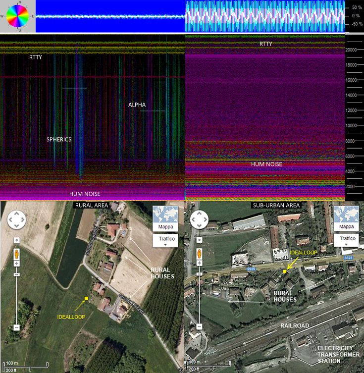
But even having said all this, a loop antenna may still be of no use for me here – Noise Annoys. Renato has an image that nicely sums up the potential problem:

renato-noise

Right now I don’t have the funds to build a loop antenna of any description (big coils use a lot of wire!) but as and when I can, I’ll probably be looking at something along the lines of Renato et al’s IdealLoop (the image above comes from that page).

I do have the components to put together some kind of little portable whip antenna (electric field) receiver, I think I’ll have a look at that next, particularly to try and get an idea of how the noise levels vary in this locale.

I’ve also got one linear Hall effect sensor, so I can have a play around with that to try and get some idea of my seismometer design’s viability.