Matching Transistors for Log/Exp Converters

Slightly off-topic again.

I’ve been looking at analog log/exp converters, primarily with music synth applications in mind. Here’s a typical Voltage Controlled Oscillator circuit, which uses a pair of transistors as part of the exponential conversion sub-circuit.  But there may well be potential for using an analog log converter to effectively improve the resolution of the ADC part of a seismic data acquisition system. Note that earthquake magnitude measurements are usually expressed as log values – e.g. in the Richter Scale, a magnitude 5 event has an amplitude 10x that of a magnitude 4 event.

There’s a useful selection of general-purpose log & exp converters in TI Application Note AN-30. When building such circuits from op amps + transistors, there are two factors that can significantly affect accuracy. The first is the effect of temperature on transistor characteristics. This is usually offset by using a temperature-sensitive (‘tempco‘) resistor. I don’t currently have any of these… The second issue is that the circuits generally involve a pair of transistors in a balanced configuration. Here it’s useful to select transistor with closely matched characteristics.

Screenshot from 2018-08-14 19-01-37

The classic circuit for testing for matching was given by none other than Dr. Robert Moog:

Screenshot from 2018-08-14 19-02-59

More sophisticated variations are described at Music from Outer Space. I’ve got a bag of 100 2N3904 transistors (about €2 from China), so I decided to have a go at finding some matched pairs.

My circuit began with a silly mistake. I’d misread Moog’s circuit, thinking that both test points were floating, not noticing that one was ground. I only realised once I’d got the thing breadboarded. No big deal, and buffering both lines did offer a bit more scope for experimentation. This is what I ended up with:

Screenshot from 2018-08-14 17-56-28

I used KiCAD for the diagram, files are on github.

The left-hand side is the same as Moog’s, just with a better op amp and 1% resistors. The right-hand side is a basic instrumentation amplifier consisting of a couple of unity-gain buffers feeding a differential amplifier with gain of 10. I initially tried a gain of 100 (using 220k rather than 22k around U1C), with a bias voltage (from a pot) on pin 5 of U1B, but this turned out to be over-sensitive, it was too easy to flip the output to one rail of the other.

I didn’t see much point in accurate reference voltages as in the MFOS designs, my 12v is regulated and after I’d left everything connected for a little while, there was too much variation in individual measurements.

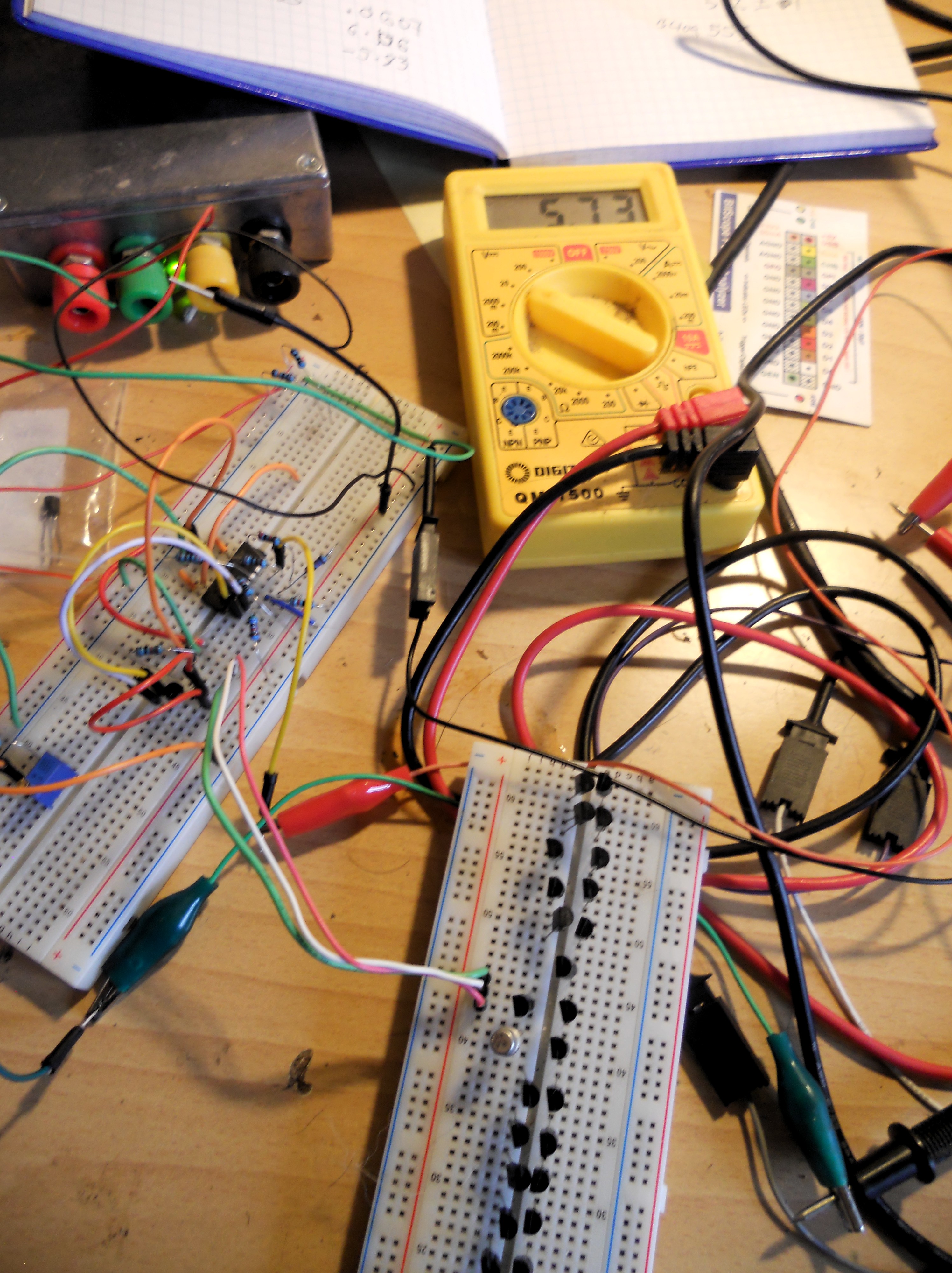
To do mass comparisons while avoiding touching the transistors (and warming them up), I stuck 40 of them into a breadboard:

DSCN1955.JPG

Moog refers to Vbe values of around 0.6V, and a target of matching within 2mV. I got similar values, 0.573 +/- 0.001V with only a couple of exceptions (even then less than 3mV difference). This seemed a little too good to be true, so I played around with things like changing the bias voltage, but still the values did seem surprising closely matched. Then a simple sanity check occurred to me. Putting a BC109 under test, this gave a value of 0.553V. Not matched to the 2N3904s.

So it looks like I got lucky 🙂


Arduino White Noise Generator

Aiming towards 16 bit.

I’ve done a video to demonstrate.

I’m still learning about what can be done with Arduinos, the main target being data acquisition for the ELFQuake project (the material in this post is all about getting stuff out). But as it involves breadboarding, I’ve got another fun target in mind – a hybrid music synth.

I’ve been reading around what other people have done with the things. For analog output, especially when considering music synthesis, there’s a problem that needs solving.

(Note I’ve been playing with an Arduino Uno – some of the other models have improved features).

The Quality Issue

Unless you’re after bitcrushed, lo-fi, glitch sounds, you need a decent sample rate and resolution. For ballpark, CD audio has a 44.1kHz sample rate, offering something under 22kHz bandwidth, see Nyquist frequency. It’s 16-bit, which means in its basic form, it has a Signal/Noise Ratio of about 96dB – though there are tricks to improve this.

A typical digital synth would use a high sample rate through a dedicated Digital-to-Analog (DAC) chip, with associated circuitry to get things into the analog domain. But as they stand though, Arduinos are very much 8 bit-based. You can get 8 bit analog signals out of a digital output pin using Pulse Wave Modulation (PWM), followed by a very simple analog filter. The easiest way is analogWrite(pin, value). But then you pretty much immediately run into the sample rate problem – I can’t remember offhand, but it’s slow. But the Arduino has 3 built-in PWM timers which can be used to get a much better rate (into the 10s of kHz, so tolerable quality should be possible).

When using the interrupts, the code starts getting obfuscated, but the principle is the same as analogWrite().
(TCCRxx refers to control registers, OC1A (Arduino pin 9) and OC1B (Arduino pin 10). For more info check the ATmega328 Datasheet.)

For the resolution, it’s possible to combine the analog from more than one PWM output. There’s some excellent material on the Open Music Labs site about this, but the basic idea is to scale the (analog) values from the PWM outputs, so eg. one is 256x the other, corresponding to the low and high 8 bits of a 16 bit signal. My basic circuit looks like this:

 
D9 ---- 1k --------------|

D10 --- 200k --- 56k ----|---> OUT
                         |
                    10n ===
                         |
                         |
                        GND

However, it can pretty much be guaranteed it won’t be 16 bits coming out of here.

The Mozzi synth project uses the same kind of configuration, but they, more realistically, only aim for max 14 bits (and kinda amusingly, their example of a 14 bit output actually only receives 8 bit values, left-shifted 6 bits, and their circuit uses a 499k/3.9k ratio, specified at 0.5% tolerance…). More generally, I doubt very much if the actual output using the kind of circuit above will get anywhere close to 14 bits.

However (2), my gut feeling is that by paying a little more attention to the analog side, it will be possible to get something like 14+ bits. I plan to experiment on this, using a few little tricks:

  • send the digital outputs through voltage-referenced comparators, so they are as close to each other in ‘raw’ state as possible
  • buffer the voltage division
  • use considerably more sophisticated integration/filtering of the PWM (perhaps independently for each output)

Noise Generation

I must admit to have been gobsmacked to have seen some folks using wavetables to generate noise. The shift register-based generators only need a handful of very low-level processor operations, they should compile down to very fast machine code. Depending where the table is stored, I wouldn’t be surprised to find out the computation is faster than the lookup. On a memory-limited device like the Arduino, I’d say it’s worth the trade-off whatever.

To be continued…

Here’s the code (I’ve left in lines that refer to the ADC, might want to use a pot to control freq or level):

*snip*


oops – I forgot about all the << and >> in there, so rather than figuring out the markup escaping here, I’ve popped it on github.

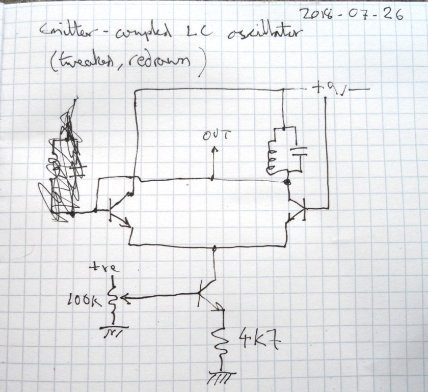
Emitter-Coupled LC Oscillator

tl;dr : the circuit seems good for high frequencies (low inductance) but for low frequencies is very dependent on the emitter current. Probably suitable for use in an inductance/capacitance meter for radio work (when coupled with a freq counter).

I did a little video.

Here’s the version I breadboarded :

DSCN1746

Here’s some analysis.

For the resonant tank I tried both the primary of a little audio transformer + 10nF and a hand-wound coil + 1nF.

DSCN1769

For the transformer + 10n, the frequency was around 850Hz, but varied a lot dependent on the current to the emitters. With about 0.7v from the pot, 30uA at the emitters, it produced a reasonable-looking sine wave (if you ignore the noise, that’s presumably just from my test setup):

Screenshot from 2018-07-27 11-39-35

Upping the voltage, and hence emitter current, distortion of the shape soon became evident (along with a significant increase in amplitude and change in pitch), until at around 3v  – er, and a lot more current, I forgot to write it down, the wave looked like this, more like wonky relaxation behaviour:

Screenshot from 2018-07-27 11-44-55

For the coil + 1n, around 0.7V at the pot, 30uA at the emitters, it produced what looks like a pretty good sine wave  at around 110kHz :

Screenshot from 2018-07-27 11-49-01

Upping the voltage again, there was still a big difference in the amplitude, but nowhere near as much in frequency. Also there looks to be considerably less distortion:

Screenshot from 2018-07-27 11-47-24

Now by my reckoning, given that the resonant frequency is 1/2*pi*sqrt(LC), this should make the inductor 2mH. In theory it should be possible to estimate the the inductance by the coil’s physical characteristics:

turns : 45 (or thereabouts)
wire diameter : 0.4mm (ditto)
coil diameter : 20cm (ditto)

But when I tried the formula here (estimating the coil length as 1.8cm), I got 55mH. Not even ballpark. I’ve tried a few online calculators but alas they seem about as reliable as my arithmetic, getting values that differ by orders of magnitude.

So I double-checked my algebra, rearranging the formula step by step, producing :

L = 1/C*(2*pi*f)^2

This again gave me a result of 2mH.

Googling a bit more, I found this page with some practical examples, including :

  L uH  Litz Size Turns Coil Width  Q-1.6MHz  Outside Wire Holes
  238    165/46    47    1-7/16       770     15/16 inch from each end

The inductance formulae on Wikipedia suggest that the induction is proportional to the square of the diameter of the coil. Which (flipping the above into cm and squaring) gives a ratio of 13:400. Leading to an inductance of 238*400/13 = 7323uH = 7mH. That’s getting more ballpark.

But it gets better – the inductance calculator linked from the page with that formula uses a completely different formula, with factors more like those I’m looking at:

latex!encoded:base64,TF97bG9vcH1cYXBwcm94IE5eezJ9XG11IF97b31cbXUgX3tyfVxsZWZ0ICggXGZyYWN7RH17Mn0gXHJpZ2h0IClcY2RvdCBcbGVmdCAoIFxsblxsZWZ0ICggICBcZnJhY3s4XGNkb3QgRH17ZH0gIFxyaWdodCApLTIgXHJpZ2h0ICk=

Screenshot from 2018-07-27 13-34-58

Yay! Near as damnit 2mH!

PS. Hmm, one thing I’d forgotten with the above calculations is the self-capacitance of the coil. Turns out that without any parallel capacitor the circuit oscillates at around 190kHz.

Frequency is proportional to the square root of the capacitance, so doubling the frequency is like quartering the capacitance…so if my head isn’t overly scrambled by now, that would give give a self-capacitance very roughly in the region of 250pF.  That feels about right, picturing the total area of those 365pF variable caps.

I’m tempted to try out a better-known LC oscillator like the Colpitts, and draw some graphs of results, buy some precision capacitors and inductors, design an Arduino-based LC meter… But this has already taken loads of time and is veering well away from what I should be doing (ELFQuake proper, something towards work-work, or even tidying the kitchen).

Fun though.


Test Gear Triumph! (Arduino to the Rescue)

Tidying up my desk a bit yesterday, I found a circuit on a breadboard I’d left hanging. Months ago I was looking into notch filters for removing mains hum, to clean up a ELF/VLF signal a wee bit. I’d put together a bootstrapped twin-T notch filter, but had got rather frustrated when testing it. I wanted to get a general idea of its response and (assuming it looked ok) tune it to 50Hz.

But I’ve only got a USB port Bitscope oscilloscope (the BS10 mixed-signal model) which does do basic frequency analysis and even has a signal generator built in. Unfortunately there’s no sweep for the sig gen, and the UI is so clunky I wound up making a little generator with an easily-twiddled knob. That still didn’t really give me what I was after in being able to clearly see what was going on.

Anyhow, today I thought I’d take another look. Got everything set up, did some manual sweeping which showed that the component values I’d used were quite a way out (more like 70Hz). But still no clear visualisation of the overall response.

Staring at the desk, pondering what to do next…there’s an Arduino Uno right in front of me. I’ve spent a fair while getting to know the things over the past few weeks. I’d noticed in passing that it had a tone() method, but hadn’t actually played with it. Ok, about 15 minutes later I had this loaded:

void setup (){
}

void loop() {
  int i;

  for (i = 35; i <= 100; i++) {
    tone(11, i);
    delay(10);
  }
}

A sweep generator!

Ok,  its frequency range is limited and it gives a square wave out. So I took the output from pin 11 and fed that to a simple RC filter (15k, 220nF) which took the buzziness down a bit. Stray harmonics aren’t that much of an issue for the current problem, and 35-100 Hz cover the range I’m looking at.

One thing the Bitscope’s waveform generator allows is the fairly accurate setting of frequency. So I set that at 50Hz and put it in one scope input, the output of my notch filter into the other. After a bit of fiddling to get levels reasonably stable, I got this:

notch

The yellow is my 50Hz reference, green the notch filter response. The harmonics on the ref are pretty dire – dunno, I guess it must be clipping. But look at that lovely notch in the green! Around 70 or so Hz, as measured before.

So this setup can help me quickly tune the notch down to where it’s needed. But that isn’t the real triumph here. What I wasn’t sure about is the rest of the response of the active notch. Where the passive notch goes from flat into a 6dB (I think) / octave drop into the notch, this version has noticeable mounds either side. Those are potentially very undesirable. If you look at the 50Hz marker here, my filter as it stands would boost that frequency. While I’m sure I can get the notch in a much better position than this, any drift (maybe due to environmental factors) could be very bad. So at the cost of less sharp notch, I reckon on balance the passive version is probably the one to go for.

PS.

A few hours on, and a bit more progress. I pulled out the active notch circuit, did calculations again and plugged in a passive one. Well, I say passive, am using a TL074 to buffer the signal.

The basic filter circuit is this:
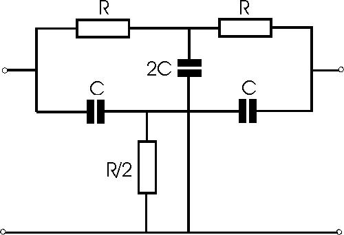
rc_twin_t

Fc = 1/(2 pi R C)

Using C = 100nF (2C just two of them in parallel) and 33k for each of the two Rs on top, a single 15k for the R/2 I got something looking like a cleanish notch, centred on 47.8Hz. It took a little trial & error. The capacitors are just off-the shelf, ceramic I think, probably 10% tolerance but came from the same batch so should be reasonable well matched. 1% resistors, again off-the shelf, same batch.

I forgot to take a screenshot…

But as I measured previously, the ambient mains hum here also contains a significant amount of 3rd harmonic, ie. 150Hz. So I did the sums again for this.

Ran into a slight snag with my setup though – when sweeping up through a reasonable range for it to go over the 150Hz target, the spectrogram display was all over the place.

But, as an alternative to sweep, you can also test freq response with white noise (or an impulse, but that’s another story). Coincidentally I was playing with a pseudorandom number generator just yesterday (for DOG-1), so knew what to look for. I found one, to which I’ve made minor tweaks –

#define speakerPin 11

unsigned long lastClick;

void setup() {
  // put your setup code here, to run once:
   pinMode(speakerPin,OUTPUT);
   lastClick = micros();   
}


/* initialize with any 32 bit non-zero  unsigned long value. */
#define LFSR_INIT  0xfeedfaceUL
/* Choose bits 32, 30, 26, 24 from  http://arduino.stackexchange.com/a/6725/6628
 *  or 32, 22, 2, 1 from 
 *  http://www.xilinx.com/support/documentation/application_notes/xapp052.pdf
 *  or bits 32, 16, 3,2  or 0x80010006UL per http://users.ece.cmu.edu/~koopman/lfsr/index.html 
 *  and http://users.ece.cmu.edu/~koopman/lfsr/32.dat.gz
 */  
#define LFSR_MASK  ((unsigned long)( 1UL<<31 | 1UL <<15 | 1UL <<2 | 1UL <<1  )) unsigned int generateNoise(){    // See https://en.wikipedia.org/wiki/Linear_feedback_shift_register#Galois_LFSRs    static unsigned long int lfsr = LFSR_INIT;  /* 32 bit init, nonzero */    /* If the output bit is 1, apply toggle mask.                                     * The value has 1 at bits corresponding                                     * to taps, 0 elsewhere. */    if(lfsr & 1) { lfsr =  (lfsr >>1) ^ LFSR_MASK ; return(1);}
   else         { lfsr >>= 1;                      return(0);}
}


void loop() {
      /* ... */
      if ((micros() - lastClick) > 500 ) { // Changing this value changes the frequency.
        lastClick = micros();
        digitalWrite (speakerPin, generateNoise());
      }

}

One tweak to use pin 11 as I’d already got that wired up. The other is rather sweet. The original code had a loop delay of 50 micros, related to the bandwidth. But that again wasn’t very clear on the spectrogram. Was nice white noise, but I’m only interested in the low end here. Making the micros 500, and letting the display accumulate for a minute, produced this:

notch-2

There’s a nice notch pretty close to 50Hz, plus my new one, near enough at 150Hz (measured at 145Hz). The peak on the left is probably just an artifact of the setup – FFT does that sort of thing. Also the relative shallowness of the second notch I reckon is at least in part to the fact that it uses a linear scale on the spectrogram.

The values I used here were C = 47n, R = 22k, pleasingly standard values (the resistors gived those capacitors calculated at 22.57k, which was handy).

I’ve just got this set up on the breadboard around a TL074 quad op amp, using 3 op amps for unity gain buffers (each with a 1M to ground). Those things have input resistance of 10^12 ohms. So I’m now thinking I might just use one of them as the input stage for an ELV/VLF receiver. The 2N3819 input stage of the BBB-4 receiver I was going to try has a 10M resistor to ground, seems like plenty of leeway for that here. Input buffer, maybe give it variable gain of something like 1-100, to these filters (perhaps adding a little more gain along the way), then use the spare op amp to drive a couple of transistors for a small speaker/headphone level output.

Just trying it with a longish wire at the input, computer speakers at out, still way too much mains-derived noise to hear any natural signals, but the difference between the different stages of the circuit is really noticeable. I’ll have to get it soldered up, battery power, take it up the fields.

And try it when there’s a thunderstorm around 🙂


Electronics World and Wireless World Articles

Last night I was looking at some possible analog circuitry again, on the Natural Radio side, specifically filters to track Schumann Resonances. The frequencies involved are around 7-30Hz. To check the response of these and other filters, I could do with a good sweep generator and a true RMS voltmeter. After sleeping on it I remembered that I worked on exactly these (and various other) mostly audio-oriented circuits in articles I wrote for this magazine, way back in 1993. Unlike digital circuits, for the everyday hacker the analog circuit state of the art hasn’t really changed from then.

These were my first published works, helped to pay for my first IBM compatible PC. I was so chuffed that I got the cover feature with The Twisted World of Non-Linear Electronics (PDF). And what a cover!

Circuits in there include exp/log converters, an RMS converter, an (audio) dynamic range processor (compressor/expander) and a couple of chaotic circuits – that make a horrible noise!

The other article I have a scan of is The Versatile World of OTAs (PDF) – I think I wrote others, but don’t appear to have scanned copies. That’s operational transconductance amplifiers.  They are closely related to regular op amps, but instead of producing an output voltage, they produce an output current. What makes them really useful is that they usually feature an additional input that controls the level of the output current. These things are found pretty much everywhere you might want something voltage-controlled, such as voltage controlled oscillators (VCOs) etc. in analog music synthesizers.

Circuits in there include a tunable active loudspeaker crossover, a couple of voltage controlled filters and a VCO. And…a bat detector. That worked a treat – made one, I with an LM380 or similar amplifier, out on a summer night, chirp, chirp!

A Quick and Dirty Audio Signal Generator

It was pretty clear that my ELFQuake setup would need fairly major mains hum filtering, especially since this location is very close to overhead power lines. This was emphasized the other day when I tried a little AM radio, all but two stations on MW were totally drowned out by hum.

When I was last experimenting with the filter circuitry I found the limited equipment I have rather frustrating. When it came to a signal generator, I didn’t have much joy using either a tablet app or the BitScope waveform generator. What I really wanted was a knob to twiddle for easy tweaking of the frequency. So a couple of days ago I spent a few hours knocking together a simple analog circuit. My requirements were essentially the twiddly knob and something approximating a sine wave. The constraints were the components I had at hand, and no desire to spend too much time over it.

What I came up with is as follows. The circuit starts with a simple triangle/square wave generator using standard analog computational elements based around op amps:

tri-osc

I’m using a TL084 quad op amp with a +/- 12v supply.

When the output of the left-hand op amp is negative, that will ramp up the integrator on the right until it flips the switch on the left (note positive feedback on that op amp). Then the integrator will ramp down until it flips the switch the other way. The frequency is simply determined by the resistors in the middle and capacitor C, as f = 1/2piRC. In practice I’ve got 6 values of C between 4u7 and 1n, producing a frequency range (measured) from about 5Hz to 200kHz. In the middle, with 100n, varying the pot in the middle gave a range from about 275Hz to 11kHz with what looked on the scope like a clean triangle wave. Switching to the top range gave a significant warping of the triangle, but I thought it might still be useful.

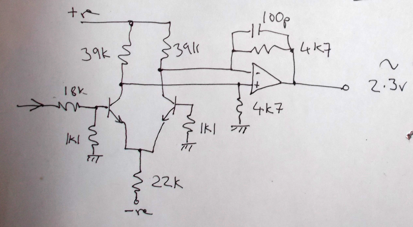
Next is a more interesting circuit, which modifies the triangle wave into something approximating a sine:

shaper

The transistors are just a couple of regular BC109s I happened to have a lot of. The transistors act as differential voltage to current converters with a nonlinear transfer function, with the op amp converting the currents back to voltages.

Here’s the cunning bit – the transfer function of the transistors is theoretically proportional to tanh, which looks like this:

TanhReal

Given the right scaling (and bias) this will have the effect of rounding over the upper and lower corners of the triangle waveform. This isn’t an entirely arbitrary choice of function. The first few terms of the Taylor Series for tanh are roughly the same as those for sine.

The actual component values were chosen pretty much by trial and error, adjusting values until the harmonic components appeared to be at a minimum on a frequency response display. Ideally the transistors should have been a matched pair in thermal contact and maybe some tweaking of the levels/balance/bias of this block might have made for a purer sine wave, but I was only after quick & dirty…

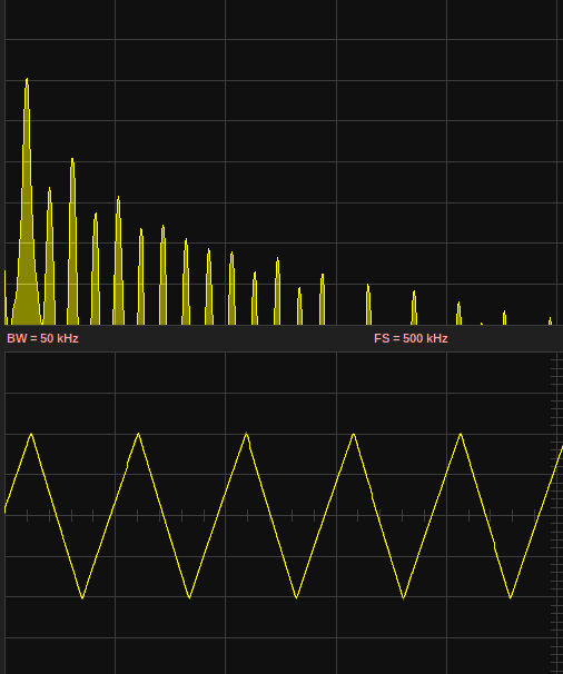
This is what the waveforms/freq plots look like (measured on a BitScope), first the square & sine from the first circuit block:

square

triangle

Here’s the shaped output:

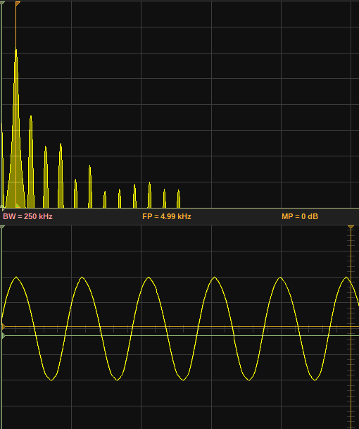
sine

Though the 2nd harmonic is still about at the same level as the triangle, but the higher harmonics do seem significantly attenuated.

According to Wikipedia, the Total Harmonic Distortion (THD) of a square wave is around 48.3% – the high harmonic levels are clear on the trace above. For a triangle wave the value is around 12.1%. I’ve not done the sums to figure out the theoretical best achievable using the tanh shaping (homework anyone?), but there is a visible improvement in the displays above. I don’t know, maybe something around 5%..?

(Incidentally, the triangle wave generator can be easily modified to generate a ramp by slipping a diode in the feedback loop).

You may have noticed I’m using a quad op amp, but only 3 of them are in use. I contemplated using the 4th as a buffer or even as the heart of a switched filter. But more useful for me I reckon, and definitely more fun, was to deploy this in a white noise generator:

noise

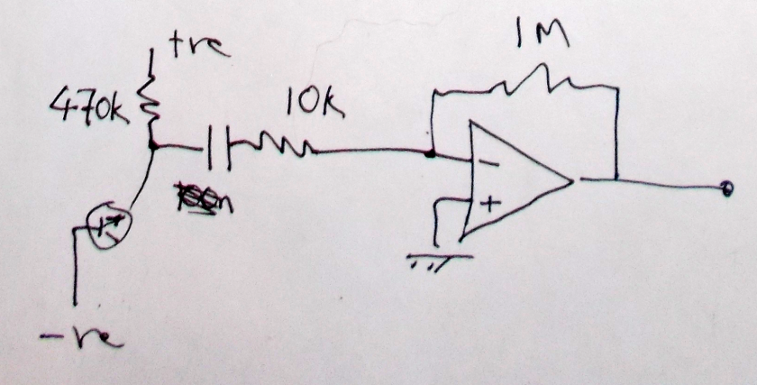
The noise source is the reverse-biased emitter-base junction of another BC109 transistor. This is simply followed by a DC-blocking capacitor and the op amp set up to give a gain of 100. I think the capacitor I used is a 100n. There was a little bleeding through of the oscillator’s signal visible, but not enough to be troublesome. The output did look remarkably wideband, only really starting to drop off gradually around 50kHz.

noise

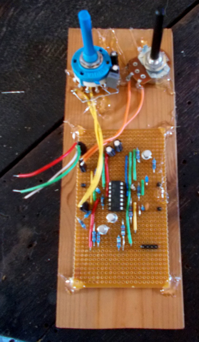
I then transferred everything to a piece of stripboard, and in true quick & dirty style mounted it on a scrap of wood:

vero

(Sorry about the blur). Incredibly, even though I put it onto the stripboard without any real planning, I only made one wiring mistake which took about 2 minutes to discover. But I was bitten by hubris when I wired up the capacitor switch – it’s a 2-pole, 6-way, and it took me ages to get the wiring right.

When I tested the sine wave output again there was a visible asymmetry – pointier on top, more rounded on the bottom. I think most likely I got the transistors the other way around. Rather than desolder/resolder them I tweaked the value of the shaper’s input resistor, adding a 1k in series with the 18k in the schematic above, which restored the balance.

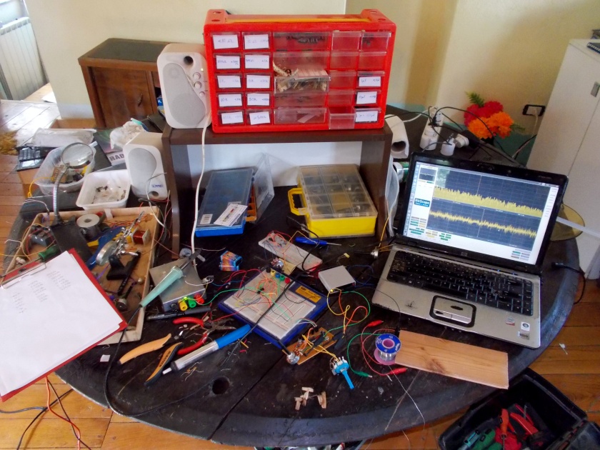
So now I have another little addition to my little electronics workbench (big coffee table)…

desk