It was pretty clear that my ELFQuake setup would need fairly major mains hum filtering, especially since this location is very close to overhead power lines. This was emphasized the other day when I tried a little AM radio, all but two stations on MW were totally drowned out by hum.
When I was last experimenting with the filter circuitry I found the limited equipment I have rather frustrating. When it came to a signal generator, I didn’t have much joy using either a tablet app or the BitScope waveform generator. What I really wanted was a knob to twiddle for easy tweaking of the frequency. So a couple of days ago I spent a few hours knocking together a simple analog circuit. My requirements were essentially the twiddly knob and something approximating a sine wave. The constraints were the components I had at hand, and no desire to spend too much time over it.
What I came up with is as follows. The circuit starts with a simple triangle/square wave generator using standard analog computational elements based around op amps:

I’m using a TL084 quad op amp with a +/- 12v supply.
When the output of the left-hand op amp is negative, that will ramp up the integrator on the right until it flips the switch on the left (note positive feedback on that op amp). Then the integrator will ramp down until it flips the switch the other way. The frequency is simply determined by the resistors in the middle and capacitor C, as f = 1/2piRC. In practice I’ve got 6 values of C between 4u7 and 1n, producing a frequency range (measured) from about 5Hz to 200kHz. In the middle, with 100n, varying the pot in the middle gave a range from about 275Hz to 11kHz with what looked on the scope like a clean triangle wave. Switching to the top range gave a significant warping of the triangle, but I thought it might still be useful.
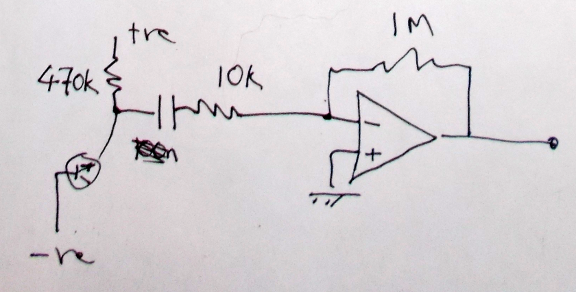
Next is a more interesting circuit, which modifies the triangle wave into something approximating a sine:
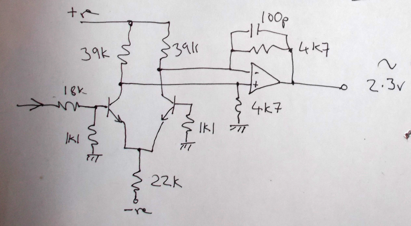
The transistors are just a couple of regular BC109s I happened to have a lot of. The transistors act as differential voltage to current converters with a nonlinear transfer function, with the op amp converting the currents back to voltages.
Here’s the cunning bit – the transfer function of the transistors is theoretically proportional to tanh, which looks like this:

Given the right scaling (and bias) this will have the effect of rounding over the upper and lower corners of the triangle waveform. This isn’t an entirely arbitrary choice of function. The first few terms of the Taylor Series for tanh are roughly the same as those for sine.
The actual component values were chosen pretty much by trial and error, adjusting values until the harmonic components appeared to be at a minimum on a frequency response display. Ideally the transistors should have been a matched pair in thermal contact and maybe some tweaking of the levels/balance/bias of this block might have made for a purer sine wave, but I was only after quick & dirty…
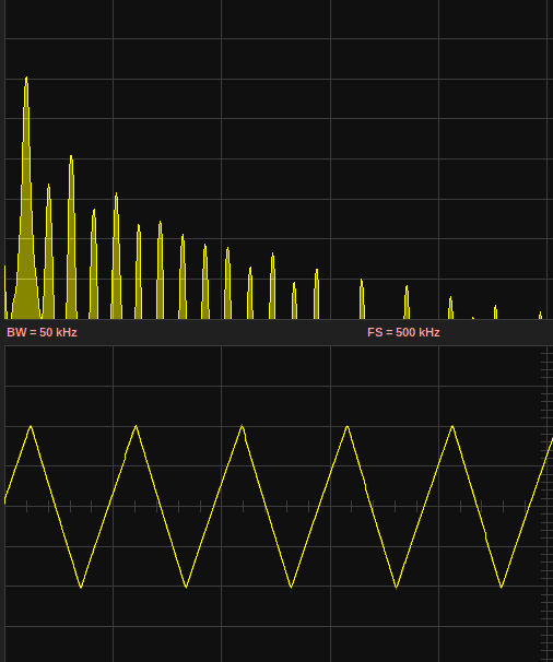
This is what the waveforms/freq plots look like (measured on a BitScope), first the square & sine from the first circuit block:

Here’s the shaped output:
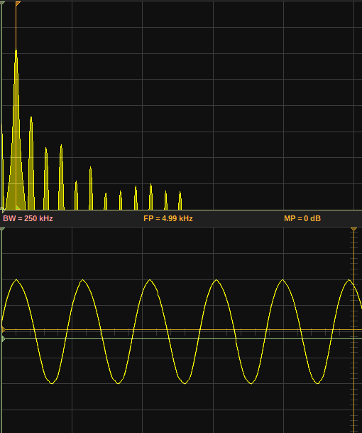
Though the 2nd harmonic is still about at the same level as the triangle, but the higher harmonics do seem significantly attenuated.
According to Wikipedia, the Total Harmonic Distortion (THD) of a square wave is around 48.3% – the high harmonic levels are clear on the trace above. For a triangle wave the value is around 12.1%. I’ve not done the sums to figure out the theoretical best achievable using the tanh shaping (homework anyone?), but there is a visible improvement in the displays above. I don’t know, maybe something around 5%..?
(Incidentally, the triangle wave generator can be easily modified to generate a ramp by slipping a diode in the feedback loop).
You may have noticed I’m using a quad op amp, but only 3 of them are in use. I contemplated using the 4th as a buffer or even as the heart of a switched filter. But more useful for me I reckon, and definitely more fun, was to deploy this in a white noise generator:
The noise source is the reverse-biased emitter-base junction of another BC109 transistor. This is simply followed by a DC-blocking capacitor and the op amp set up to give a gain of 100. I think the capacitor I used is a 100n. There was a little bleeding through of the oscillator’s signal visible, but not enough to be troublesome. The output did look remarkably wideband, only really starting to drop off gradually around 50kHz.

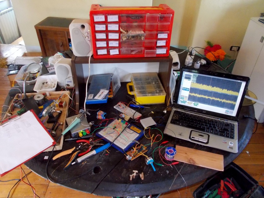
I then transferred everything to a piece of stripboard, and in true quick & dirty style mounted it on a scrap of wood:
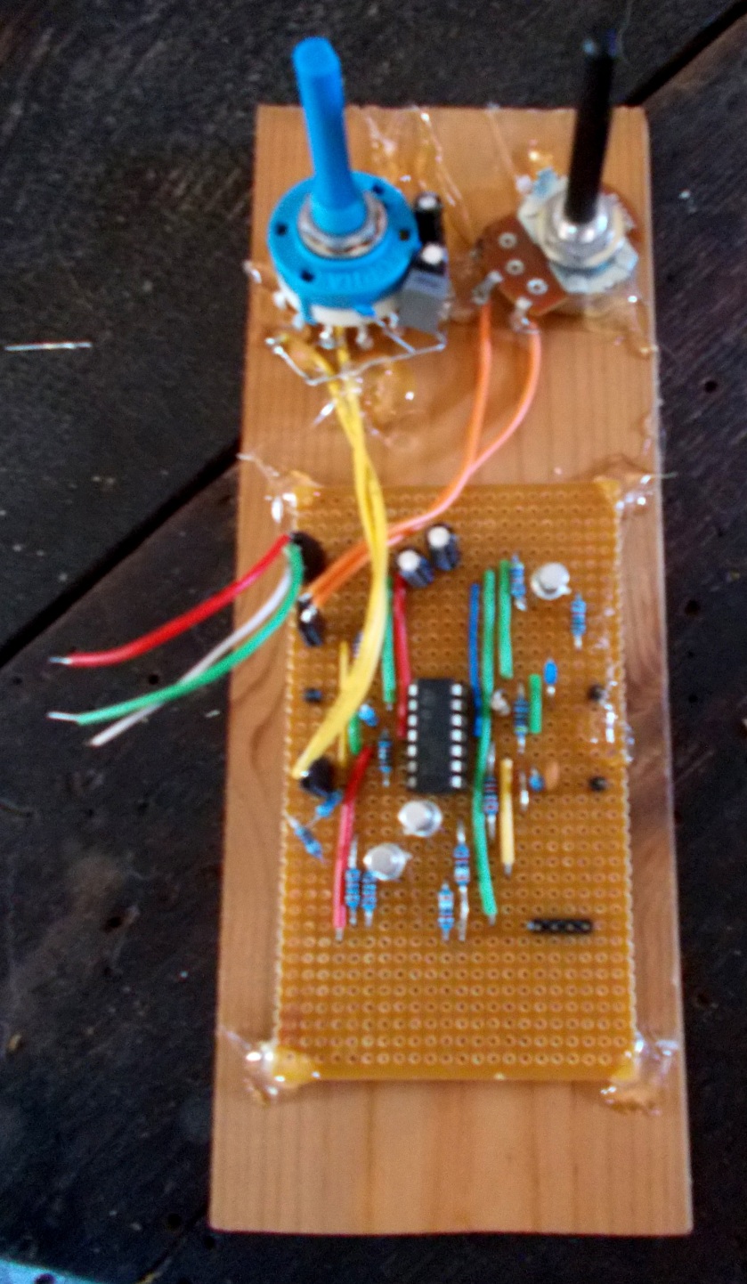
(Sorry about the blur). Incredibly, even though I put it onto the stripboard without any real planning, I only made one wiring mistake which took about 2 minutes to discover. But I was bitten by hubris when I wired up the capacitor switch – it’s a 2-pole, 6-way, and it took me ages to get the wiring right.
When I tested the sine wave output again there was a visible asymmetry – pointier on top, more rounded on the bottom. I think most likely I got the transistors the other way around. Rather than desolder/resolder them I tweaked the value of the shaper’s input resistor, adding a 1k in series with the 18k in the schematic above, which restored the balance.
So now I have another little addition to my little electronics workbench (big coffee table)…