Arduino ESP8266 ‘Shiald’, step by step

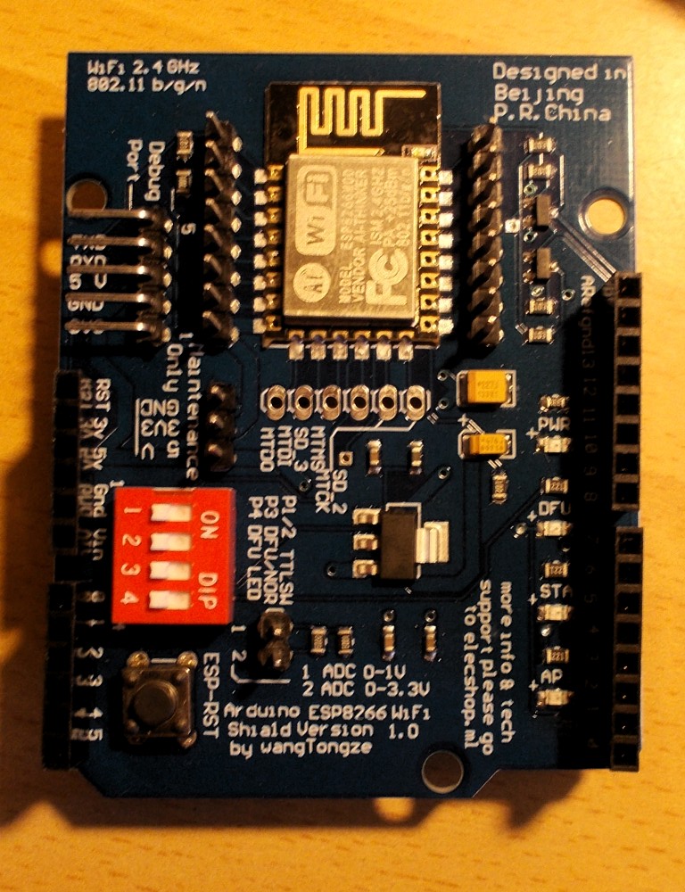
A little while ago I ordered a couple of Arduino Uno cards along with a couple of ESP8266 WiFi shields. It being my first hands-on with Arduinos, I was rather naive in my choice of shields. I got mine from banggood.com when they were listed as “ESP8266 ESP-12E UART WIFI Wireless Shield TTL Converter For Arduino UNO R3 Mega“, but while figuring out how to use them I found that various other budget tech vendors sell them. Their identifying feature is a charming little typo printed on the PCB :

Arduino ESP8266 WiFi Shiald Version 1.0 by WangTongze

DSCN0002

The major problem is that the only official documentation is in Chinese (Mandarin?), something I haven’t a clue about. But by trawling the web and with a lot of trial and error I was eventually able to get code running on the card. I’ve written the process up spread across previous posts here, but it is rather convoluted, so for future ref. I’m pulling it together here. If you haven’t already bought one of these shields, you may well be better off getting something like a Wemos card.

Requirements

  • Arduino ESP8266 WiFi Shiald Version 1.0 by WangTongze
  • Computer with Arduino IDE loaded (I’m using a regular laptop with Ubuntu OS)
  • USB-TTL level serial converter – NB. I didn’t have one of these, but it turns out to be straightforward to use an Arduino Uno as a pass-through converter
  • USB cable, jumper leads (4 with a socket on one end)

Flashing Firmware

I must admit I don’t know if this step is entirely necessary, there may well be a quicker approach. But it worked for me, and is useful for resetting the card.

Using Arduino as USB-Serial Converter for the ‘Shiald’

The wiring is as follows :

Shiald Debug TX  => Uno Pin 1 (TX)
Shiald Debug RX  => Uno Pin 0 (RX)
Shiald Debug 5V  => Uno 5V
Shiald Debug GND => Uno GND
Uno Reset        => Uno GND

(Uno USB => Computer USB)

Flashing

Before connecting the Arduino to the computer, set the DIP switches on the Shiald as follows:

1 Off
2 Off
3 On
4 On

The following I got from the Wemos page Tutorial – Returning a Wemos D1 Mini to Factory Firmware (AT) :

I had to tweak my paths a little bit, I forget the details, but whatever it took to get esptool.py running from the shell.

The script needed tweaking for the appropriate paths. Run:

ls /dev/tty*

–  and the appropriate port should be obvious on the resulting list. My version of the script looks like this:

#!/bin/sh
# ESPToolDir="$HOME/Downloads/esptool"
FirmwareDir="$HOME/Arduino/ESP8266_NONOS_SDK"
cd "$FirmwareDir" 
port=/dev/ttyACM0
if [ ! -c $port ]; then
 port=/dev/ttyACM1
fi
if [ ! -c $port ]; then
 echo "No device appears to be plugged in. Stopping."
fi
printf "Writing AT firmware in 3..."
sleep 1; printf "2..."
sleep 1; printf "1..."
sleep 1; echo "done."
echo "Erasing the flash first"
"esptool.py" --port $port erase_flash

"esptool.py" --chip esp8266 --port $port \
 write_flash -fm dio -ff 20m -fs detect \
 0x0000 "$FirmwareDir/bin/boot_v1.7.bin" \
 0x01000 "$FirmwareDir/bin/at/512+512/user1.1024.new.2.bin" \
 0x3fc000 "$FirmwareDir/bin/esp_init_data_default_v08.bin" \
 0x7e000 "$FirmwareDir/bin/blank.bin" \
 0x3fe000 "$FirmwareDir/bin/blank.bin"

echo "Done."

The messages given by esptool.py are pleasingly informative, but I found I have to press the reset button on the Shiald when the message got to:

...
Hard resetting...
esptool.py v2.2.1
Connecting...

The original script suggested using miniterm to check this had worked. I used the Arduino IDE. First unplug the USB and set the DIP switchesto all Off.

After plugging back in again & launching the IDE, go to Tools -> Port and choose whatever looks right. Under Tools -> Board choose NodeMCU 1.0 (ESP 12E module). Then go to Tools -> Serial Monitor.

In the serial monitor, set the baud rate to 112500 and then click reset on the Shiald.

You should get a message that ends in ‘ok‘.

At this point you should be able to communicate with the Shiald using AT commands. Two useful things:

AT+UART_DEF=9600,8,1,0,0

This will flip the baud rate down to 9600.

AT+GMR

Gives the versions of various things.

At this point it should be possible to upload software to the Shiald (with the DIP switches Off, Off, On, On) from the Arduino IDE.

Tools -> Board NodeMCU 1.0 (ESP12)


I’ve found that it often takes several attempts (and hits of the reset switch) to get a successful upload, no matter what the baud rate.

e.g. this minimal web server:

#include <ESP8266WiFi.h>
#include <WiFiClient.h>
#include <ESP8266WebServer.h>
const char* ssid = "AllPay Danny";
const char* password = "not this";
ESP8266WebServer server(80); // HTTP server on port 80

IPAddress ip(192, 168, 0, 14); // where xx is the desired IP Address
IPAddress gateway(192, 168, 0, 1); // set gateway to match your network
IPAddress subnet(255, 255, 255, 0); // set subnet mask to match your network

void setup() {
 Serial.begin(9600); 
 WiFi.disconnect(); // Disconnect AP

 WiFi.config(ip, gateway, subnet);

 WiFi.mode(WIFI_STA); 
 WiFi.begin(ssid, password); // Connect to WIFI network
// Wait for connection
 while (WiFi.status() != WL_CONNECTED) {
 delay(500);
 Serial.println(".");
 }
 Serial.print("Connected to ");
 Serial.println(ssid);
 Serial.print("IP address: ");
 Serial.println(WiFi.localIP());
server.on("/", [](){
 server.send(200, "text/plain", "Hello World");
 });
server.begin(); // Start HTTP server
 Serial.println("HTTP server started.");
}
void loop() {
 server.handleClient();
}

Pointing a browser at the chosen IP address should now work.

There’s a complication to comms between the Arduino and the Shiald. It seems the serial Tx/Rx lines of the ESP8266 connect to ports 1 & 2 on the Shiald – the Arduino’s Tx/Rx.

Again, I’m not really sure how essential this is, but it certainly works to wire other ports on the Arduino to the serial on the Shiald and use the SoftwareSerial lib. For reliability a baud rate of 9600 seems advisible.

Here’s a little example that worked for me:

#include <SoftwareSerial.h>
SoftwareSerial mySerial(2, 3); // RX, TX on Arduino
void setup() {
 Serial.begin(9600);
 mySerial.begin(9600);
}
void loop() {
 if (mySerial.available()) {
 String msg = mySerial.readString();
 Serial.print("Data received: ");
 Serial.println(msg);
 }
}

Remember before uploading to remove the jumpers and change the board settings in the Arduino IDE.

At runtime, the following wiring worked for me:

Arduino   | Shiald

GND       - Debug GND
+5v       - Debug 5v
Digital 2 - Digital 0
Digital 3 - Digital 1

For my own application I want to be able to read values from the Analog Ins of the Arduino (6) and ESP8266 (1) and expose these (and one or two other little things) on a web server over Wifi. I’ve made a bit more progress towards this, will upload code to this project’s GitHub repo once I’ve tweaked to hide passwords.

So…this is my current setup:

DSCN0004

The lower part is a Shiald piggybacking an Arduino Uno, the upper another Arduino acting as a serial interface direct to the Shiald. Each Arduino is going to a USB port on the laptop.

The wiring – the Shiald has its pins 1 & 2 bent out of line and connected instead via jumpers to pins 2 & 3 on the host Arduino. The Arduino acting as a serial interface has is as above, less the power lines.

For writing code to the Shiald, the DIP switches are at Off, Off, On, On. At runtime they’re at On, On, Off, Off.

I’m still using the Arduino IDE, flipping between USB port and board (Arduino Uno/NodeMCU 1.0).

It’s a bit of a pain flipping between the configs, but takes less time than uploading a reasonably long program to the Shiald, so I can’t really complain.


Arduino front end ideas

So, as mentioned in previous posts, I reckon it’s worth trying to use Arduinos as front-end microcontrollers for this project, as shown in the block diagram here. An Arduino Uno has 6 analog inputs, and the ESP8266 WiFi card which I plan to use has one. These are quite limited – 10 bit ADCs with bandwidth that at best may go up into a few kHz. As such, while they should be ok for picking up seismic data, they fall far short for the ELF/VLF radio capture which should really go up to the region of 20kHz.

On the seismic side, I think a first pass worth trying is a home-hacked sensitive, one axis sensor, plus a 3 axis gyro and a 3 axis accelerometer. I’ll come back to this is a while – I need to research & buy the gyro & accelerometers. But I have all the components for an attempt at a useful radio subsystem, provisional design as follows…

vlf-filter-based

Starting at top left, the blue circle represents the actual ELF/VLF radio receiver. This will be some kind of antenna, picking up the electric field with a frequency range from somewhere probably in the 100s of mHz up to around say 200kHz. A good starting point for this seems to be the BBB-4 VLF Receiver. It’s a relatively simple 2-transistor design, with a high impedance FET input followed by a bit of further amplification provided by a regular BJT.

A major problem, as mentioned here before is mains hum interference. It seems that as well as the 50Hz fundamental, there’s also a significant amount of the 3rd harmonic at 150Hz. So I propose using notch filters at these frequencies (also in that earlier post). Given what will follow in the circuit, I don’t think these need to be very high Q/narrow, just enough to prevent these parts of the input swamping everything else, saturating what comes next. These filters are shown as the yellow block in the diagram.

Next comes a bank of bandpass filters. The Arduino+ESP8266 offer 7 channels, so I propose having the first being relatively broadband, pretty much just a buffer for everything coming from the receiver (post notches). After each of these will be a simple peak level detector, shown above as a diode & capacitor. The level on these will be passed onto the Arduino/ESP8266 analogue inputs.

(The diagram is simplified a bit. The gain of the different stages will need to be figured out, additional gain/buffering/level-shifting/limiting stages will be needed).

The key references on ELF/VLF radio precursors to earthquakes are vlf.it (note especially the OPERA project) and a chapter in Roberto Romero’s Radio Nature book. Alas, it seems that research is fairly inconclusive (and in places contradictory). Radio frequencies from the milliHertz right up to microwave are mentioned, may contain useful information. But keeping things simple is a major consideration here, so I’ll stick to somewhere a bit below audio up to a bit above. Yes, this project is experimental…

I intend to do a bit more examination of the signals that appear in VLF before going further, though whatever, the choice of frequency bands at this point has to be fairly arbitrary. Pretty much decades in the audio range seem a reasonable starting point. So on top of 0. broadband, here goes:

  1. 0.01 … 10Hz
  2. 20Hz
  3. 200Hz
  4. 2kHz
  5. 20kHz
  6. 40kHz … 200kHz

The question of how narrow/broad to make the filters for best results is another question that I reckon can only be answered with the help of experimentation. But it is possible to make pragmatic educated guesses. I intend using general-purpose op amps for implementation.

At the bottom end of (1.), I suspect it’ll be more effort that it’s worth to worry too much about LF roll off, a simple buffered CR filter, should be adequate. Effectively just DC blocking. For the top end of (1.), a straightforward two op amp LP filter should be fine. For 2. – 5. bandpass filters made from 2 op amps should make a fair starting point. Regarding the steepness of their curves, Butterworth configurations (maximally flat in passband) keep design straightforward.

You may notice that 3. + are at multiples of 50Hz. But I’m hoping that using standard value/tolerance components will make enough offset to alleviate the hum harmonics. E.g. using the Sallen-Key circuit (this is a low pass, but shows what I’m talking about):

Sallen-Key_Lowpass_Example.svg

This gives fc = 15.9 kHz and Q = 0.5, subject to component tolerances (typical inexpensive capacitors are +/-10%). The kind of values that are probably close enough to the decades above to usefully split ranges, but (hopefully) offcentre for the 50Hz harmonics.

I don’t know if I’ve mentioned it before, but as the radio receiver needs to be as far away as possible from power lines (which will likely be determined by my WiFi range), I’m intending using little solar panels feeding rechargeable batteries for power.

While on the subject, I reckon it’ll also be worthwhile adding data from other environmental sensors, notably for temperature and acoustic noise (a mic). Pretty straightforward for Arduinos. Variations in this data may be unlikely to be useful as earthquake precursors, but they will almost certainly play a part in environmental noise picked up by the radio & seismic sensors. My hope is to get a Deep Learning configuration together that will in effect subtract this from the signals of interest.

ESP8266 Shiald Progress!

I’m really tired, but while trying to watch TV got to thinking about the Wifi board I’ve been playing with (described in previous post). I’d got as far as loading firmware that allowed it to speak AT codes. Couldn’t resist having a quick look at what could be done next. Luckily I went to my bookmarks first rather than looking at my notes here, because there was a page I must have bookmarked early on and forgotten about : Arduino UNO + ESP8266 ESP-12E UART WIFI Shield. It contains code for a minimal web server.

Looking at an image in this post reveals that the Shield there is there very same Shiald [sic] I have. Only problem, the author uses a USB-serial adapter to talk to it, something I don’t have. But wait – I found a way of rigging the Arduino to act as such an adapter (previous post).

I saw somewhere, and confirmed (by using a tablet to scan for WiFi networks) that the default IP address for the Shiald is rather an obscure one, off my local subnet anyway. But a bit of googling gave me the info necessary to set the IP to something else.

After fiddling a bit with the baud rate, a little blue light started flashing next to the ESP8266 chip, and it worked!

In the IDE:

Screenshot from 2018-02-07 23-07-57

In the Serial console:

Screenshot from 2018-02-07 23-11-12

Screenshot from 2018-02-07 23-11-35

And in a browser! Woo-hoo!

Screenshot from 2018-02-07 22-45-33

Here’s my tweaked version of the script:

#include <ESP8266WiFi.h>
#include <WiFiClient.h>
#include <ESP8266WebServer.h>
const char* ssid = "AllPay Danny";
const char* password = "not this";
ESP8266WebServer server(80); // HTTP server on port 80

IPAddress ip(192, 168, 0, 14); // where xx is the desired IP Address
IPAddress gateway(192, 168, 0, 1); // set gateway to match your network
IPAddress subnet(255, 255, 255, 0); // set subnet mask to match your network

void setup() {
 Serial.begin(115200); 
 WiFi.disconnect(); // Disconnect AP
 
 WiFi.config(ip, gateway, subnet);
 
 WiFi.mode(WIFI_STA); 
 WiFi.begin(ssid, password); // Connect to WIFI network
// Wait for connection
 while (WiFi.status() != WL_CONNECTED) {
 delay(500);
 Serial.println(".");
 }
 Serial.print("Connected to ");
 Serial.println(ssid);
 Serial.print("IP address: ");
 Serial.println(WiFi.localIP());
server.on("/", [](){
 server.send(200, "text/plain", "Hello World");
 });
server.begin(); // Start HTTP server
 Serial.println("HTTP server started.");
}
void loop() {
 server.handleClient();
}

The blog post goes on to Part 2 Upload code to Arduino, which I’ll try next – when I’m properly rested 🙂

PS.

Just tried this Part 2 bit, essentially comms between Shiald & Arduino. It nearly worked :

Data received: . .
Conoected to AllPay Danoy
IP address: 092.168.0.04C!⸮⸮⸮⸮ٕɁ⸮⸮

I’ve read somewhere that the Software Serial struggles at high baud rates, and this example is using 115200 so presumably that’s the problem. Bit of tweaking required.

PPS.

I flipped the baud rate in the code based on that in the blog post to 9600, and with the Arduino as serial converter uploaded the new code to the Shiald (at 115200 baud), set as NodeMCU 1.0. Uploading took a good few attempts, but finally it worked.

I also changed the Arduino part of the code to use different ports :

#include <SoftwareSerial.h>
SoftwareSerial mySerial(2, 3); // RX, TX on Arduino
void setup() {
 Serial.begin(9600);
 mySerial.begin(9600);
}
void loop() {
 if (mySerial.available()) {
 String msg = mySerial.readString();
 Serial.print("Data received: ");
 Serial.println(msg);
 }
}

The wiring I now have as :

Arduino   | Shiald

GND       - Debug GND
+5v       - Debug 5v
Digital 2 - Digital 0
Digital 3 - Digital 1

The switches on the Shiald are at (1,2,3,4) On, On, Off, Off.

And finally, the Hello World is still visible on the IP address I set. And what’s more, in the serial monitor (now set to 9600 baud) I see:

Connected to AllPay Danny
IP address: 192.168.0.14
HTTP server started.

Yay! It all works.

So…

Next

First thing I should do is pull together all the various bits from the last post and this, with relevant material from linked pages, and write it up as a from scratch to here procedure. I won’t remember, and also anyone that buys the same boards will stand a chance of getting things going.

Then I need to think about what I’m going to do on the analog/sensor side. What I can do with the hardware I’ve got is fairly limited – a key factor being the speed of the data acquisition on the Arduino. But I should have the necessary for me to build something that operates end-to-end with essentially the same topology as my target design.

Regarding code on the Arduino & Shiald, the next steps will be to :

  1. Get the data from the single Analog Input on the Shiald, buffer/filter it and expose it on a local web server. With a little analog pre-amp & filter this should be enough for a single-channel seismometer.
  2. Do the code necessary on a regular computer to access and do something with the data from the web server on the Shiald.
  3. Get the data from the 6 Analog Inputs on the Arduino, buffer/filter it, transfer it to the Shiald and again expose on a local web server. I might well try the analog bandpass filter idea mentioned in my previous post.
  4. As 2. but for the 6 channels.

A global job to put together in parallel with the above is the code necessary for self-description of the units to provide status information alongside the data. RDF and Web of Things time!

So now I’ve got fairly fun jobs to get on with on every side of this project :

  1. Sensor hardware
  2. Arduino/Shiald software
  3. Comms/post-processing software – I can get on with the Deep Learning bits using online sources, haven’t looked at that for weeks
  4. Notification system – hook the Deep Learning bit output to Twitter

I may have to get the dice out…

//// note to self

danny@lappie:/dev$ esptool.py --port ttyACM0 --baud 9600 flash_id
esptool.py v2.2.1
Connecting........_____....._____
Detecting chip type... ESP8266
Chip is ESP8266EX
Uploading stub...
Running stub...
Stub running...
Manufacturer: c8
Device: 4016
Detected flash size: 4MB
Hard resetting...

Arduino – initial experiences

skip to Arduino/WiFi bit, also Issues Raised and a Cunning Plan

Requirements & Constraints

On the hardware side of this project, I want to capture local seismic and ELF/VLF radio data. I’ve given myself two major constraints: it should be simple; it should be low cost. These constraints are somewhat conflicting. For example, on the seismic side, a simple approach would be to purchase a Raspberry Shake, an off-the-shelf device based on a Raspberry Pi and an (off-the-shelf) geophone. Unfortunately, these gadgets start at $375 USD, and that’s only for one dimension (and there may be software licensing issues). I want to capture 3D data, and want to keep the price comfortably under $100. Note that project non-constraints are absolute measurement, calibration etc. So the plan is to hack something. I’m taking rather a scattergun approach to the hardware – find as many approaches as are feasible and try them out.

Both the seismic and radio sensor subsystems have particular requirements when it comes to physical location. The seismic part should ideally be firmly attached to local bedrock; the radio part should be as far away as possible from interference – mains hum being the elephantine wasp in the room. For my own installation this will probably mean bolting the seismic part to my basement floor (which is largely on bedrock) and having the radio part as far up the fields as I can get it.

What seems the most straightforward starting point is to feed data from the sensors into a local ADC, pass this through a microcontroller into a WiFi transceiver, then pick this up on the home network. (WiFi range may well be an issue – but I’ll cross that bridge when I come to it).

The two microcontroller systems that seem most in the frame due to their relatively low cost are the aforementioned Raspberry Pi and the Arduino family. For a first pass, something Arduino-based seems the best bet – they are a lot cheaper than the Pis, and have the advantage of having multiple ADCs built in (compared to the Pi’s none – though there are straightforward add-ons).

Arduino Fun

Quite a while ago I ordered a couple of Arduino Unos and WiFi shields from Banggood, a China-based retailer of low cost stuff. My only prior experience with Arduinos was when my brother was building something MIDI-related and hit a code problem. He mailed me on the offchance and amusingly I was able to solve the problem in my reply – it was a fairly easy bit of C (I hadn’t done any other C for years, but coding is coding).

I instantly fell in love with the Arduino boards (actually a clone by GeekCreit). After very little time at all I was able to use the Arduino IDE to get some of the example code running on one of the devices. Light goes on, light goes off, light goes on… Very user friendly.

ESP8266 Nightmares

In my naivety, I assumed the WiFi shields would be as straightforward. Most probably are, but the ones I ordered have been distinctly painful so far. But I can at least put slow progress so far down as a learning experience. Essentially the ones I got have several issues. The story so far:

The boards I got are labeled “Arduino ESP8266 WiFi Shiald Version 1.0 by WangTongze”. Yup, that’s ‘Shiald’, not auspicious. The first major issue was that the only official documentation was in Chinese (mandarin?). I wasted a lot of time trying to treat them as more standard boards. But then found two extremely helpful blog posts by Claus : Using ESP8266 Shield ESP-12E (elecshop.ml) by WangTongze with an Arduino Uno and Arduino ESP8266 WiFi Shield (elecshop.ml) by WangTongze Comparison.

The first of these posts describes a nifty little setup, using an Arduino board as a converter from USB to TTL level RS232 that the Shiald can understand (I didn’t think to order such an adapter). It looks like this:

arduino1

By default the Shiald plugs its serial TX/RX pins to the Arduino’s, which does seem a design flaw. But this can (apparently) be flipped to using software serial via regular digital I/O pins on the Uno. A key thing needed is to tell the Shiald to use 9600 baud rather than its default 115200. The setup above allows this. This part worked for me.

However, at this point, after bending the TX/RX pins out of the way on the Shiald and plugging it in on top of the Uno (with jumpers to GPIO for TX/RX), I couldn’t talk to it. So going back to Claus’s post, he suggests updating the Shiald’s firmware. Following his links, I tried a couple, ended up with the setup spewing gibberish (at any baud rate).

At this point – after a good few hours yesterday, I was ready to cut my losses with the WiFi Shialds. I’d mentioned to danbri that I was struggling with these cards and he mentioned that he’d had the recommendation (from Libby) of Wemos cards. So I started having a look around at what they were. As it happens, they have a page on their wiki Tutorial – Returning a Wemos D1 Mini to Factory Firmware (AT). The D1 uses the same ESP8266 chips as my Shiald, so this morning, nothing to lose, adjusted the script and gave it a shot. Going back to the setup in the pic (with DIP switches tweaked as Claus suggests) it worked! (Tip – along the way of flashing, I had to press the Shiald’s reset button a couple of times).

arduino-at

So far so pleasing – I thought I might have bricked the board.

(See also ESP8266 Wifi With Arduino Uno and Nano)

After this I’d tried with the Shiald mounted on top of the Arduino in a good few configurations with various different software utilities, haven’t yet got everything talking to everything else, but this does feel like progress.

Issues Raised and a Cunning Plan

Sooo… these Shialds have been rather thieves of time, but it’s all learning, innit.

These bits of play have forced me into reading up on the Arduinos a bit more. For this project, a key factor is the ADC sample rate. It seems that the maximum achievable for a single ADC is around 9kHz (with 10 bit precision). That should be plenty for the seismic sensor. The radio sensor is another matter. I’d like to be able to cover up to say 20kHz, which means a sampling rate of at least 40kHz. I’m still thinking about this one, but one option would be to use an ADC shield – these ones from Mayhew Labs look plenty – though getting the fast data along to WiFi could well be an issue (intermediate baud rates). If necessary, some local processing could be a workaround. I have been intending to present the radio data to the neural network(s) as spectrograms so maybe eg. running an FFT on the Arduino may be feasible.

Along similar lines, I may have a Cunning Plan, that is to shift some of the processing from digital to analog. This is likely to need a fair amount of research & experimentation, but the practical circuitry could be very straightforward. It seems at least plausible that the earthquake precursors are going to occur largely in particular frequency regions. The Arduino has 6 analog inputs. So imagine the radio receiver being followed by 6 bandpass filters, each tuned around where precursors may be expected. A simple diode & (leaky) capacitor peak level detector for each of these could provide a very crude spectrogram, at a rate the Arduino could easily handle. Op amp BP filters are straightforward and cheap, so an extra $5 on the analog side might save $40 and a oad more work afterward.

Regarding the research – a key source is (of course) Renato Romero’s vlf.it, notably the OPERA project – although that does seem to focus at the low end of potential frequencies.