Modular Synth Reconfigured

Mostly pics for now, it took me ages to fit the new power supply & test, did have other things to do today…

A 1 minute video of the testing

This is what the (mostly) analog (moderately) modular desk looks like now. Loads of lovely rack space!

These two are modules I put together myself. First was the one on the right, two attenuators (a pot, I probably DC blocked so a couple of caps too) and two amplifiers (a couple of op amps each. I believe I used kcad for the schematic, should be around somewhere, but was pretty much datasheet stuff.

The one on the left, dual low pass gate, was very experimental. Vactrol-based, entirely passive. Surprisingly useful for very few components. The front panel was also a (failed) experiment.

This is just a passive switch box I made to quickly change monitoring setup. Included here because the front panel technique is the one that has worked the best. Design on computer (I used LibreOffice Draw, it’s good for block diagrams etc). Do a rough printout to use as a template, cut/drill 3mm aluminium to match. Do a high quality printout on glossy paper. Laminate. Cut out and glue to the aluminium, cut out the holes with a scalpel.

This is the Chatterbox, something I put together just before I started looking into modular. ESP32-based with decent 2-channel DAC, has MIDI in, and I even got WebSockets over Wifi going so it could be controlled from a web page. The ESP32 also has Bluetooth support, but I haven’t played with that yet).

Although I love the look, the case took way longer than I’d have liked to get together. Eurorack time!

It also revealed loads of little issues, eg. those push switches are hard work.

A bigger issue was that my code got messy. I’m not very experienced with C++ and the dual cores of the ESP32 did my head in a bit.

So next I made a version of another old idea, the Dreamachine. Like the Chatterbox this needed some controls and some DSP (for modulating the lights and generating white/pink noise for audio). My main aim was making a reasonably solid code framework. Instead of analogue pots I used rotary encoders and added a little display, only used the internal DACs.

I’ve got most of the coding done. The main frameworky idea was to have ESP32’s core 0 running all the UI code, core 1 doing the DSP. This seems to be working nicely, should be a good basis for other synthesis on the ESP32.

(The cable connects the device to an battery pack attached underneath).

I’ve got a bunch of analog and digital modules at various stages of design. More on those another day.

Happy New Year!

A good time to take stock, huddled in front of the fire.

Boo!

As is often the case, I’ve been moving more slowly on this project than I’d have liked. Lack of resources is a continuing problem, but my own tendency to procrastinate has been by far the biggest obstacle to progress. On top of this, my main dev computer packed up recently, so until I can get that fixed or replaced I’m getting things set up again on an old laptop. Frustrating.

Three Steps Forward…

My strategy of taking a multi-pronged approach has had its pros and cons. I’ve got a prototype VLF receiver mostly built and have spent quite a lot of time playing around with Arduinos and related devices. On the software side – which is really the novel aspect of this project – I did make reasonable progress, getting together a provisional system design and some of the implementation. But then stalled. My desire to build hardware to allow local data collection has been something of a distraction, when there’s nothing stopping me from working with data from INGV and VLF.it.

Plans.

Looking ahead, I really need to reboot myself on the software dev. The ultimate target for running code will be nothing more sophisticated than this laptop. But for exploring algorithms and probably NN training, pre-optimisation, I reckon using cloud services will be my best bet. Concurrently I can look at some of the side prongs that I want to include in the system as a whole – notably web publication of data and automatic generation of Twitter notifications.

As everyone that’s worked on a solo project knows, I’ve also got a lot more material in my head or at best sketched in notebooks that needs writing up. How often has the New Year Resolution been : “Write more docs.”.

Mini-Seismograph

On the hardware side, until I’ve got my income a bit better sorted out I am pretty much limited to rather a scattergun approach using what ever components I have at hand. As well as finishing off the mostly-built VLF receiver, I’ve also got the bits for a basic seismograph. It’ll essentially be :

  •  ESP32microcontroller + comms :  core of the subsystem, handling the acquisition and preprocessing of data, which it will expose using a basic web server, accessible from the local network (the ESP32 includes WiFi connectivity).
  • MPU6050sensors : accelerometer +gyroscope : a tiny MEMS device, connected over I2C.
  • MicroSD carddata logging : experience shows that 100% connectivity is implausible, so some local history is very desirable
  • Tiny RTC cardrealtime clock :  the comms will be async, so accurate local timestamps are a must.

The ESP32 is a remarkably capable little device and I’m reasonably confident of the viability of interfacing the peripherals. Hopefully just a matter of plodding through example code for each, tweaking as needed.

The MPU6050 sensors are much less sensitive than those of typical seismometers. Only events with significant magnitude are likely to be detectable. It remains to be seen, but I have my suspicions that having 2 different types of sensor in there mean it will, with a bit of wrangling, be possible to get more effective sensitivity than the individual sensor data would yield. Whatever, once the wiring and code is in place for this setup, it should be trivial to extend it to use a more sensitive sensor. (Note the Raspberry Shake 4D configuration.)

Also…

I’ve got a little tangential project on the go. ELFQuake is in essence about trying to model aspects of a physical system : Earth geology and its electronically-detectable artifacts. Creating an analogue in software that captures enough to be able to make useful predictions. Also I’m increasingly convinced that the design of analog circuits between the sensors and standard data acquisition elements (ADCs etc) will have a major impact on the potential success of the system. Putting these points together, it shouldn’t seem that off the wall that I’ve been working on the design of an analog computer. (I must admit I also want to play with chaotic systems, this is something I’ve been messing about with for years).


Connecting all the World’s Circuits

I’ve been a bit frustrated in recent weeks by electronic circuit design tools. The typical process is to draw out the circuit schematic, run simulations and then generate/draw PCB layouts etc. Many of the tools (especially on *nix) use SPICE format to represent the circuit topology between the different operations.

The tools I’ve looked at so far all appear to have one major flaw or another.

To give just three examples:

  • gEDA – rather out-of-date, clunky UI
  • KiCad – the netlists it generates aren’t quite compatible with SPICE (circuit emulation) tools
  • Fritzing – the netlists it generate are nothing like SPICE format (I believe it uses XML)

So, the go-to representation as far as I’m concerned for pretty much anything is the Resource Description Framework (RDF). So I had a quick search around looking to see if anyone had looked at SPICE in RDF before. D’oh! I found a SPICE vocab I’d roughed out on GitHub around 2011. Jeez, my memory.

So it turns out that most of what I might have put in this post, I’ve already written up in Adding SPICE to the Semantic Web.

Just a couple of things to add here.

Why not use JSON? 

Since I did that post, JSON has become fairly ubiquitous, I’m sure it’s now most coders’ go-to representation of data. But in its basic form it isn’t Web-friendly, in the sense that it doesn’t natively support links.

Links could make things much easier to share and find: circuits, components, datasheets etc (the description of the circuit in RDF would include URLs for the components, which in turn could be associate with their characteristics, with their datasheets, etc etc).

There’s even a commercial angle. Given the list of components, a bill of materials can be generated. But typically nowadays you have to trawl through vendors to find suitable suppliers. But in RDF, the component could be associated with a vendor, with fields like the price etc. A distributed SPARQL query could figure much of this stuff out automatically.

Ok, why not use JSON? – There’s JSON-LD, which is an RDF representation, it’s JSON with links included.

One other idea. In the middle of typing this, I had a brief chat with Reto, told him what I was typing. He wondered whether there might be a role for inference (which is a good question, given the existence of RDF/OWL  reasoners). Hmmm, my immediate response was, yeah, maybe something like consistency-checking a circuit for dangling wires. But Reto made the point that OWL probably wouldn’t be the best reasoning for the job, this might be more of a SHACL use case.


Noise and Chaos on the Arduino

Off-topic. I needed to get my head into gear for work-work, and over the weekend I had an odd little idea I wanted to try. So here’s a quick & dirty write-up and video.

After playing with Arduino White Noise the other week, I did a bit of reading up on the Colors of Noise. Particularly interesting is Pink Noise, in which “each octave (halving/doubling in frequency) carries an equal amount of noise energy… This is in contrast with white noise which has equal intensity per frequency interval.”. It occurs a lot in nature, but is not entirely trivial to synthesize either using analog or digital processing. (Here’s a fairly accurate analog pink noise generator circuit).

Mind wandering, this led me onto chaotic signals. These are remarkably easy to slip into in the analog domain, essentially all you need is a non-linear system with feedback (and the right parameters)  – see this old magazine write-up on non-linear circuits. They also easy to generate in the digital. The best known system is probably the Lorenz Attractor,

But there are much simpler discrete systems, notable the Logistic Map. This is just:

x1 = r * x0 * (1-x0)

where r is a constant, x0 is the current value of x, x1 the next value. With values of r between about 3.6 and 4, the thing goes chaotic.

This was pretty easy to plug into the same skeleton code I used for Arduino white noise generation. The result was the same distinctive kind of racket that the analog circuits generate.  To provide a bit of control, I put a pot. on an analog input, scaling the read value between 0-1 and adding it to 3 to provide an interesting value range for r.

But what I wanted to play with wasn’t just this. One way of generating electronic (and mechanic) chaos is to drive an otherwise periodic system with a periodic signal, as in the chaotic double pendulum. But with pink noise on my mind, I was curious to see what would happen if a chaotic system was driven with white noise.

The code, again using the skeleton I already had, was straightforward. I added another pot. to another analog input to determine the level of the noise signal.

My code is a real hacky mess at the moment, mostly due to hopping between integer and float values, and scaling, but the core of it looks like this (effectively inside a loop):

  // Shift register-based random number generator (white noise)
  unsigned lsb = lfsr & 1;   /* Get LSB (i.e., the output bit). */
  lfsr >>= 1;                /* Shift register */
  lfsr ^= (-lsb) & 0xB400u;

  // control values
  noise_level = analogRead(NOISE_LEVEL_PIN); // will be 0 - 1023
  r_value = analogRead(R_VALUE_PIN);

  r = 3 + ((float)r_value) / 1024;

  noise_scale = ((float)noise_level) / 2048;

  x_scale = 1 - noise_scale;

  noise = noise_scale * ((float)lfsr) / 65536;

  x = x_scale * x + noise;

  // logistic map
  x = r * x * (1 - x);


  // the value to output
  temp3 = (uint16_t)(x * 65536); // scale & cast

I’ve no idea where this is going…

Screenshot from 2018-09-04 14-00-45

VLF Receiver Oddments

I’m doing a little more on a simple handheld VLF receiver I’ve been working on. For an electric field receiver all that’s essentially required is a whip antenna and a high input impedance, high gain, audio frequency amplifier. Some filtering is desirable to limit the bandwidth and cut the noise of mains hum.

I’ve already soldered up the input & filter stages, yesterday breadboarded the output stage – an amplifier to drive a little speaker/headphones. But I’d forgotten a key consideration, how much overall gain the thing should have.

A quick google later, found this rather nice poster on NASA’s site, “Building and Testing a Portable VLF Receiver“.

Screenshot from 2018-08-28 18-54-27

It doesn’t have the schematic – I expect it’s one of their INSPIRE models. But it does have what I was looking for. Signal is of the order of microvolts, their overall gain is x1500 – rather more than I’ve allowed for so far. There’s a feedback resistor change in my near future.

First though I reckon I’ll draw up the circuit as it stands (in KiCAD). I can figure out the gain bits from there, and simulate. I also need to check roll-off at the frequency extremes (call it 20Hz & 20kHz). Hmm, gain of 1500, that’ll be tempting to stability problems.

When I was looking for the gain requirements yesterday, I opened a bunch of the results in browser tabs. I found what I was looking for in the first, but am pleased I didn’t close the others. While vlf.it is the site for all things Radio Nature, I did stumble on some material I hadn’t seen before.

This page is notable : VLF Natural Radio Reception at techlib.com. It features a variety of simple receiver designs. One piece of utter genius jumped out at me. The major problem with VLF reception is interference noise, so ideally you want to situate the receiver a long way from sources of that – eg. houses, computers… Which is a pain if you want to record/analyze the signal. Here the author bends a baby monitor transmitter, replacing the mic with a VLF preamp. Voila, instant remote receiver.

I love this :

The antenna was horizontal and near the ground under my truck for this recording. That turned out to be a questionable location, by the way! Not only did several neighbors become alarmed by it, but a couple of police officers also spotted the thing. I must admit, it does have a bomb-like appearance! It spent the rest of the night under an overturned flower pot with the VLF antenna sticking out the little drain hole in the bottom.“.

Another very promising site I ran across, have still to read, is Larry’s Very Low Frequency Site. Looks like there’s some good material.

For now, back to the KiCAD.


Matching Transistors for Log/Exp Converters

Slightly off-topic again.

I’ve been looking at analog log/exp converters, primarily with music synth applications in mind. Here’s a typical Voltage Controlled Oscillator circuit, which uses a pair of transistors as part of the exponential conversion sub-circuit.  But there may well be potential for using an analog log converter to effectively improve the resolution of the ADC part of a seismic data acquisition system. Note that earthquake magnitude measurements are usually expressed as log values – e.g. in the Richter Scale, a magnitude 5 event has an amplitude 10x that of a magnitude 4 event.

There’s a useful selection of general-purpose log & exp converters in TI Application Note AN-30. When building such circuits from op amps + transistors, there are two factors that can significantly affect accuracy. The first is the effect of temperature on transistor characteristics. This is usually offset by using a temperature-sensitive (‘tempco‘) resistor. I don’t currently have any of these… The second issue is that the circuits generally involve a pair of transistors in a balanced configuration. Here it’s useful to select transistor with closely matched characteristics.

Screenshot from 2018-08-14 19-01-37

The classic circuit for testing for matching was given by none other than Dr. Robert Moog:

Screenshot from 2018-08-14 19-02-59

More sophisticated variations are described at Music from Outer Space. I’ve got a bag of 100 2N3904 transistors (about €2 from China), so I decided to have a go at finding some matched pairs.

My circuit began with a silly mistake. I’d misread Moog’s circuit, thinking that both test points were floating, not noticing that one was ground. I only realised once I’d got the thing breadboarded. No big deal, and buffering both lines did offer a bit more scope for experimentation. This is what I ended up with:

Screenshot from 2018-08-14 17-56-28

I used KiCAD for the diagram, files are on github.

The left-hand side is the same as Moog’s, just with a better op amp and 1% resistors. The right-hand side is a basic instrumentation amplifier consisting of a couple of unity-gain buffers feeding a differential amplifier with gain of 10. I initially tried a gain of 100 (using 220k rather than 22k around U1C), with a bias voltage (from a pot) on pin 5 of U1B, but this turned out to be over-sensitive, it was too easy to flip the output to one rail of the other.

I didn’t see much point in accurate reference voltages as in the MFOS designs, my 12v is regulated and after I’d left everything connected for a little while, there was too much variation in individual measurements.

To do mass comparisons while avoiding touching the transistors (and warming them up), I stuck 40 of them into a breadboard:

DSCN1955.JPG

Moog refers to Vbe values of around 0.6V, and a target of matching within 2mV. I got similar values, 0.573 +/- 0.001V with only a couple of exceptions (even then less than 3mV difference). This seemed a little too good to be true, so I played around with things like changing the bias voltage, but still the values did seem surprising closely matched. Then a simple sanity check occurred to me. Putting a BC109 under test, this gave a value of 0.553V. Not matched to the 2N3904s.

So it looks like I got lucky 🙂


Arduino White Noise Generator

Aiming towards 16 bit.

I’ve done a video to demonstrate.

I’m still learning about what can be done with Arduinos, the main target being data acquisition for the ELFQuake project (the material in this post is all about getting stuff out). But as it involves breadboarding, I’ve got another fun target in mind – a hybrid music synth.

I’ve been reading around what other people have done with the things. For analog output, especially when considering music synthesis, there’s a problem that needs solving.

(Note I’ve been playing with an Arduino Uno – some of the other models have improved features).

The Quality Issue

Unless you’re after bitcrushed, lo-fi, glitch sounds, you need a decent sample rate and resolution. For ballpark, CD audio has a 44.1kHz sample rate, offering something under 22kHz bandwidth, see Nyquist frequency. It’s 16-bit, which means in its basic form, it has a Signal/Noise Ratio of about 96dB – though there are tricks to improve this.

A typical digital synth would use a high sample rate through a dedicated Digital-to-Analog (DAC) chip, with associated circuitry to get things into the analog domain. But as they stand though, Arduinos are very much 8 bit-based. You can get 8 bit analog signals out of a digital output pin using Pulse Wave Modulation (PWM), followed by a very simple analog filter. The easiest way is analogWrite(pin, value). But then you pretty much immediately run into the sample rate problem – I can’t remember offhand, but it’s slow. But the Arduino has 3 built-in PWM timers which can be used to get a much better rate (into the 10s of kHz, so tolerable quality should be possible).

When using the interrupts, the code starts getting obfuscated, but the principle is the same as analogWrite().
(TCCRxx refers to control registers, OC1A (Arduino pin 9) and OC1B (Arduino pin 10). For more info check the ATmega328 Datasheet.)

For the resolution, it’s possible to combine the analog from more than one PWM output. There’s some excellent material on the Open Music Labs site about this, but the basic idea is to scale the (analog) values from the PWM outputs, so eg. one is 256x the other, corresponding to the low and high 8 bits of a 16 bit signal. My basic circuit looks like this:

 
D9 ---- 1k --------------|

D10 --- 200k --- 56k ----|---> OUT
                         |
                    10n ===
                         |
                         |
                        GND

However, it can pretty much be guaranteed it won’t be 16 bits coming out of here.

The Mozzi synth project uses the same kind of configuration, but they, more realistically, only aim for max 14 bits (and kinda amusingly, their example of a 14 bit output actually only receives 8 bit values, left-shifted 6 bits, and their circuit uses a 499k/3.9k ratio, specified at 0.5% tolerance…). More generally, I doubt very much if the actual output using the kind of circuit above will get anywhere close to 14 bits.

However (2), my gut feeling is that by paying a little more attention to the analog side, it will be possible to get something like 14+ bits. I plan to experiment on this, using a few little tricks:

  • send the digital outputs through voltage-referenced comparators, so they are as close to each other in ‘raw’ state as possible
  • buffer the voltage division
  • use considerably more sophisticated integration/filtering of the PWM (perhaps independently for each output)

Noise Generation

I must admit to have been gobsmacked to have seen some folks using wavetables to generate noise. The shift register-based generators only need a handful of very low-level processor operations, they should compile down to very fast machine code. Depending where the table is stored, I wouldn’t be surprised to find out the computation is faster than the lookup. On a memory-limited device like the Arduino, I’d say it’s worth the trade-off whatever.

To be continued…

Here’s the code (I’ve left in lines that refer to the ADC, might want to use a pot to control freq or level):

*snip*


oops – I forgot about all the << and >> in there, so rather than figuring out the markup escaping here, I’ve popped it on github.

Test Gear Triumph! (Arduino to the Rescue)

Tidying up my desk a bit yesterday, I found a circuit on a breadboard I’d left hanging. Months ago I was looking into notch filters for removing mains hum, to clean up a ELF/VLF signal a wee bit. I’d put together a bootstrapped twin-T notch filter, but had got rather frustrated when testing it. I wanted to get a general idea of its response and (assuming it looked ok) tune it to 50Hz.

But I’ve only got a USB port Bitscope oscilloscope (the BS10 mixed-signal model) which does do basic frequency analysis and even has a signal generator built in. Unfortunately there’s no sweep for the sig gen, and the UI is so clunky I wound up making a little generator with an easily-twiddled knob. That still didn’t really give me what I was after in being able to clearly see what was going on.

Anyhow, today I thought I’d take another look. Got everything set up, did some manual sweeping which showed that the component values I’d used were quite a way out (more like 70Hz). But still no clear visualisation of the overall response.

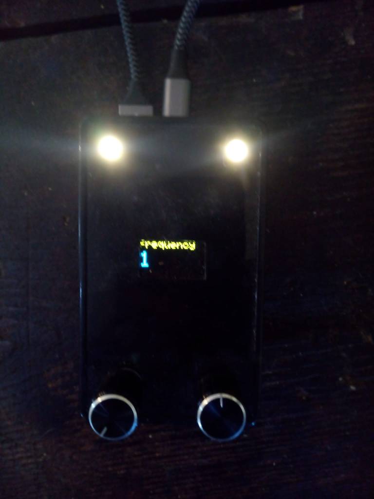
Staring at the desk, pondering what to do next…there’s an Arduino Uno right in front of me. I’ve spent a fair while getting to know the things over the past few weeks. I’d noticed in passing that it had a tone() method, but hadn’t actually played with it. Ok, about 15 minutes later I had this loaded:

void setup (){
}

void loop() {
  int i;

  for (i = 35; i <= 100; i++) {
    tone(11, i);
    delay(10);
  }
}

A sweep generator!

Ok,  its frequency range is limited and it gives a square wave out. So I took the output from pin 11 and fed that to a simple RC filter (15k, 220nF) which took the buzziness down a bit. Stray harmonics aren’t that much of an issue for the current problem, and 35-100 Hz cover the range I’m looking at.

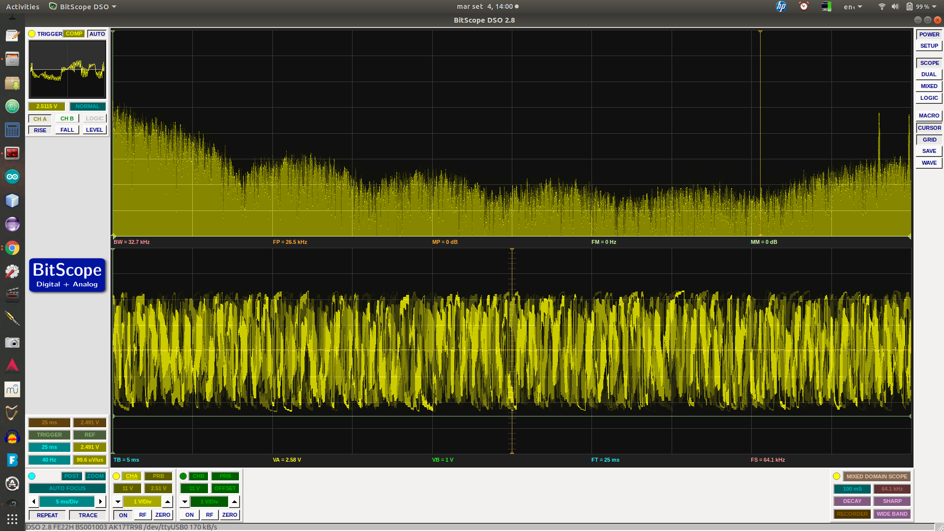
One thing the Bitscope’s waveform generator allows is the fairly accurate setting of frequency. So I set that at 50Hz and put it in one scope input, the output of my notch filter into the other. After a bit of fiddling to get levels reasonably stable, I got this:

notch

The yellow is my 50Hz reference, green the notch filter response. The harmonics on the ref are pretty dire – dunno, I guess it must be clipping. But look at that lovely notch in the green! Around 70 or so Hz, as measured before.

So this setup can help me quickly tune the notch down to where it’s needed. But that isn’t the real triumph here. What I wasn’t sure about is the rest of the response of the active notch. Where the passive notch goes from flat into a 6dB (I think) / octave drop into the notch, this version has noticeable mounds either side. Those are potentially very undesirable. If you look at the 50Hz marker here, my filter as it stands would boost that frequency. While I’m sure I can get the notch in a much better position than this, any drift (maybe due to environmental factors) could be very bad. So at the cost of less sharp notch, I reckon on balance the passive version is probably the one to go for.

PS.

A few hours on, and a bit more progress. I pulled out the active notch circuit, did calculations again and plugged in a passive one. Well, I say passive, am using a TL074 to buffer the signal.

The basic filter circuit is this:

rc_twin_t

Fc = 1/(2 pi R C)

Using C = 100nF (2C just two of them in parallel) and 33k for each of the two Rs on top, a single 15k for the R/2 I got something looking like a cleanish notch, centred on 47.8Hz. It took a little trial & error. The capacitors are just off-the shelf, ceramic I think, probably 10% tolerance but came from the same batch so should be reasonable well matched. 1% resistors, again off-the shelf, same batch.

I forgot to take a screenshot…

But as I measured previously, the ambient mains hum here also contains a significant amount of 3rd harmonic, ie. 150Hz. So I did the sums again for this.

Ran into a slight snag with my setup though – when sweeping up through a reasonable range for it to go over the 150Hz target, the spectrogram display was all over the place.

But, as an alternative to sweep, you can also test freq response with white noise (or an impulse, but that’s another story). Coincidentally I was playing with a pseudorandom number generator just yesterday (for DOG-1), so knew what to look for. I found one, to which I’ve made minor tweaks –

#define speakerPin 11

unsigned long lastClick;

void setup() {
  // put your setup code here, to run once:
   pinMode(speakerPin,OUTPUT);
   lastClick = micros();   
}


/* initialize with any 32 bit non-zero  unsigned long value. */
#define LFSR_INIT  0xfeedfaceUL
/* Choose bits 32, 30, 26, 24 from  http://arduino.stackexchange.com/a/6725/6628
 *  or 32, 22, 2, 1 from 
 *  http://www.xilinx.com/support/documentation/application_notes/xapp052.pdf
 *  or bits 32, 16, 3,2  or 0x80010006UL per http://users.ece.cmu.edu/~koopman/lfsr/index.html 
 *  and http://users.ece.cmu.edu/~koopman/lfsr/32.dat.gz
 */  
#define LFSR_MASK  ((unsigned long)( 1UL<<31 | 1UL <<15 | 1UL <<2 | 1UL <<1  )) unsigned int generateNoise(){    // See https://en.wikipedia.org/wiki/Linear_feedback_shift_register#Galois_LFSRs    static unsigned long int lfsr = LFSR_INIT;  /* 32 bit init, nonzero */    /* If the output bit is 1, apply toggle mask.                                     * The value has 1 at bits corresponding                                     * to taps, 0 elsewhere. */    if(lfsr & 1) { lfsr =  (lfsr >>1) ^ LFSR_MASK ; return(1);}
   else         { lfsr >>= 1;                      return(0);}
}


void loop() {
      /* ... */
      if ((micros() - lastClick) > 500 ) { // Changing this value changes the frequency.
        lastClick = micros();
        digitalWrite (speakerPin, generateNoise());
      }

}

One tweak to use pin 11 as I’d already got that wired up. The other is rather sweet. The original code had a loop delay of 50 micros, related to the bandwidth. But that again wasn’t very clear on the spectrogram. Was nice white noise, but I’m only interested in the low end here. Making the micros 500, and letting the display accumulate for a minute, produced this:

notch-2

There’s a nice notch pretty close to 50Hz, plus my new one, near enough at 150Hz (measured at 145Hz). The peak on the left is probably just an artifact of the setup – FFT does that sort of thing. Also the relative shallowness of the second notch I reckon is at least in part to the fact that it uses a linear scale on the spectrogram.

The values I used here were C = 47n, R = 22k, pleasingly standard values (the resistors gived those capacitors calculated at 22.57k, which was handy).

I’ve just got this set up on the breadboard around a TL074 quad op amp, using 3 op amps for unity gain buffers (each with a 1M to ground). Those things have input resistance of 10^12 ohms. So I’m now thinking I might just use one of them as the input stage for an ELV/VLF receiver. The 2N3819 input stage of the BBB-4 receiver I was going to try has a 10M resistor to ground, seems like plenty of leeway for that here. Input buffer, maybe give it variable gain of something like 1-100, to these filters (perhaps adding a little more gain along the way), then use the spare op amp to drive a couple of transistors for a small speaker/headphone level output.

Just trying it with a longish wire at the input, computer speakers at out, still way too much mains-derived noise to hear any natural signals, but the difference between the different stages of the circuit is really noticeable. I’ll have to get it soldered up, battery power, take it up the fields.

And try it when there’s a thunderstorm around 🙂


Electronics World and Wireless World Articles

Last night I was looking at some possible analog circuitry again, on the Natural Radio side, specifically filters to track Schumann Resonances. The frequencies involved are around 7-30Hz. To check the response of these and other filters, I could do with a good sweep generator and a true RMS voltmeter. After sleeping on it I remembered that I worked on exactly these (and various other) mostly audio-oriented circuits in articles I wrote for this magazine, way back in 1993. Unlike digital circuits, for the everyday hacker the analog circuit state of the art hasn’t really changed from then.

These were my first published works, helped to pay for my first IBM compatible PC. I was so chuffed that I got the cover feature with The Twisted World of Non-Linear Electronics (PDF). And what a cover!

Circuits in there include exp/log converters, an RMS converter, an (audio) dynamic range processor (compressor/expander) and a couple of chaotic circuits – that make a horrible noise!

The other article I have a scan of is The Versatile World of OTAs (PDF) – I think I wrote others, but don’t appear to have scanned copies. That’s operational transconductance amplifiers.  They are closely related to regular op amps, but instead of producing an output voltage, they produce an output current. What makes them really useful is that they usually feature an additional input that controls the level of the output current. These things are found pretty much everywhere you might want something voltage-controlled, such as voltage controlled oscillators (VCOs) etc. in analog music synthesizers.

Circuits in there include a tunable active loudspeaker crossover, a couple of voltage controlled filters and a VCO. And…a bat detector. That worked a treat – made one, I with an LM380 or similar amplifier, out on a summer night, chirp, chirp!

Arduino ESP8266 ‘Shiald’, step by step

A little while ago I ordered a couple of Arduino Uno cards along with a couple of ESP8266 WiFi shields. It being my first hands-on with Arduinos, I was rather naive in my choice of shields. I got mine from banggood.com when they were listed as “ESP8266 ESP-12E UART WIFI Wireless Shield TTL Converter For Arduino UNO R3 Mega“, but while figuring out how to use them I found that various other budget tech vendors sell them. Their identifying feature is a charming little typo printed on the PCB :

Arduino ESP8266 WiFi Shiald Version 1.0 by WangTongze

DSCN0002

The major problem is that the only official documentation is in Chinese (Mandarin?), something I haven’t a clue about. But by trawling the web and with a lot of trial and error I was eventually able to get code running on the card. I’ve written the process up spread across previous posts here, but it is rather convoluted, so for future ref. I’m pulling it together here. If you haven’t already bought one of these shields, you may well be better off getting something like a Wemos card.

Requirements

  • Arduino ESP8266 WiFi Shiald Version 1.0 by WangTongze
  • Computer with Arduino IDE loaded (I’m using a regular laptop with Ubuntu OS)
  • USB-TTL level serial converter – NB. I didn’t have one of these, but it turns out to be straightforward to use an Arduino Uno as a pass-through converter
  • USB cable, jumper leads (4 with a socket on one end)

Flashing Firmware

I must admit I don’t know if this step is entirely necessary, there may well be a quicker approach. But it worked for me, and is useful for resetting the card.

Using Arduino as USB-Serial Converter for the ‘Shiald’

The wiring is as follows :

Shiald Debug TX  => Uno Pin 1 (TX)
Shiald Debug RX  => Uno Pin 0 (RX)
Shiald Debug 5V  => Uno 5V
Shiald Debug GND => Uno GND
Uno Reset        => Uno GND

(Uno USB => Computer USB)

Flashing

Before connecting the Arduino to the computer, set the DIP switches on the Shiald as follows:

1 Off
2 Off
3 On
4 On

The following I got from the Wemos page Tutorial – Returning a Wemos D1 Mini to Factory Firmware (AT) :

I had to tweak my paths a little bit, I forget the details, but whatever it took to get esptool.py running from the shell.

The script needed tweaking for the appropriate paths. Run:

ls /dev/tty*

–  and the appropriate port should be obvious on the resulting list. My version of the script looks like this:

#!/bin/sh
# ESPToolDir="$HOME/Downloads/esptool"
FirmwareDir="$HOME/Arduino/ESP8266_NONOS_SDK"
cd "$FirmwareDir" 
port=/dev/ttyACM0
if [ ! -c $port ]; then
 port=/dev/ttyACM1
fi
if [ ! -c $port ]; then
 echo "No device appears to be plugged in. Stopping."
fi
printf "Writing AT firmware in 3..."
sleep 1; printf "2..."
sleep 1; printf "1..."
sleep 1; echo "done."
echo "Erasing the flash first"
"esptool.py" --port $port erase_flash

"esptool.py" --chip esp8266 --port $port \
 write_flash -fm dio -ff 20m -fs detect \
 0x0000 "$FirmwareDir/bin/boot_v1.7.bin" \
 0x01000 "$FirmwareDir/bin/at/512+512/user1.1024.new.2.bin" \
 0x3fc000 "$FirmwareDir/bin/esp_init_data_default_v08.bin" \
 0x7e000 "$FirmwareDir/bin/blank.bin" \
 0x3fe000 "$FirmwareDir/bin/blank.bin"

echo "Done."

The messages given by esptool.py are pleasingly informative, but I found I have to press the reset button on the Shiald when the message got to:

...
Hard resetting...
esptool.py v2.2.1
Connecting...

The original script suggested using miniterm to check this had worked. I used the Arduino IDE. First unplug the USB and set the DIP switchesto all Off.

After plugging back in again & launching the IDE, go to Tools -> Port and choose whatever looks right. Under Tools -> Board choose NodeMCU 1.0 (ESP 12E module). Then go to Tools -> Serial Monitor.

In the serial monitor, set the baud rate to 112500 and then click reset on the Shiald.

You should get a message that ends in ‘ok‘.

At this point you should be able to communicate with the Shiald using AT commands. Two useful things:

AT+UART_DEF=9600,8,1,0,0

This will flip the baud rate down to 9600.

AT+GMR

Gives the versions of various things.

At this point it should be possible to upload software to the Shiald (with the DIP switches Off, Off, On, On) from the Arduino IDE.

Tools -> Board NodeMCU 1.0 (ESP12)


I’ve found that it often takes several attempts (and hits of the reset switch) to get a successful upload, no matter what the baud rate.

e.g. this minimal web server:

#include <ESP8266WiFi.h>
#include <WiFiClient.h>
#include <ESP8266WebServer.h>
const char* ssid = "AllPay Danny";
const char* password = "not this";
ESP8266WebServer server(80); // HTTP server on port 80

IPAddress ip(192, 168, 0, 14); // where xx is the desired IP Address
IPAddress gateway(192, 168, 0, 1); // set gateway to match your network
IPAddress subnet(255, 255, 255, 0); // set subnet mask to match your network

void setup() {
 Serial.begin(9600); 
 WiFi.disconnect(); // Disconnect AP

 WiFi.config(ip, gateway, subnet);

 WiFi.mode(WIFI_STA); 
 WiFi.begin(ssid, password); // Connect to WIFI network
// Wait for connection
 while (WiFi.status() != WL_CONNECTED) {
 delay(500);
 Serial.println(".");
 }
 Serial.print("Connected to ");
 Serial.println(ssid);
 Serial.print("IP address: ");
 Serial.println(WiFi.localIP());
server.on("/", [](){
 server.send(200, "text/plain", "Hello World");
 });
server.begin(); // Start HTTP server
 Serial.println("HTTP server started.");
}
void loop() {
 server.handleClient();
}

Pointing a browser at the chosen IP address should now work.

There’s a complication to comms between the Arduino and the Shiald. It seems the serial Tx/Rx lines of the ESP8266 connect to ports 1 & 2 on the Shiald – the Arduino’s Tx/Rx.

Again, I’m not really sure how essential this is, but it certainly works to wire other ports on the Arduino to the serial on the Shiald and use the SoftwareSerial lib. For reliability a baud rate of 9600 seems advisible.

Here’s a little example that worked for me:

#include <SoftwareSerial.h>
SoftwareSerial mySerial(2, 3); // RX, TX on Arduino
void setup() {
 Serial.begin(9600);
 mySerial.begin(9600);
}
void loop() {
 if (mySerial.available()) {
 String msg = mySerial.readString();
 Serial.print("Data received: ");
 Serial.println(msg);
 }
}

Remember before uploading to remove the jumpers and change the board settings in the Arduino IDE.

At runtime, the following wiring worked for me:

Arduino   | Shiald

GND       - Debug GND
+5v       - Debug 5v
Digital 2 - Digital 0
Digital 3 - Digital 1

For my own application I want to be able to read values from the Analog Ins of the Arduino (6) and ESP8266 (1) and expose these (and one or two other little things) on a web server over Wifi. I’ve made a bit more progress towards this, will upload code to this project’s GitHub repo once I’ve tweaked to hide passwords.

So…this is my current setup:

DSCN0004

The lower part is a Shiald piggybacking an Arduino Uno, the upper another Arduino acting as a serial interface direct to the Shiald. Each Arduino is going to a USB port on the laptop.

The wiring – the Shiald has its pins 1 & 2 bent out of line and connected instead via jumpers to pins 2 & 3 on the host Arduino. The Arduino acting as a serial interface has is as above, less the power lines.

For writing code to the Shiald, the DIP switches are at Off, Off, On, On. At runtime they’re at On, On, Off, Off.

I’m still using the Arduino IDE, flipping between USB port and board (Arduino Uno/NodeMCU 1.0).

It’s a bit of a pain flipping between the configs, but takes less time than uploading a reasonably long program to the Shiald, so I can’t really complain.