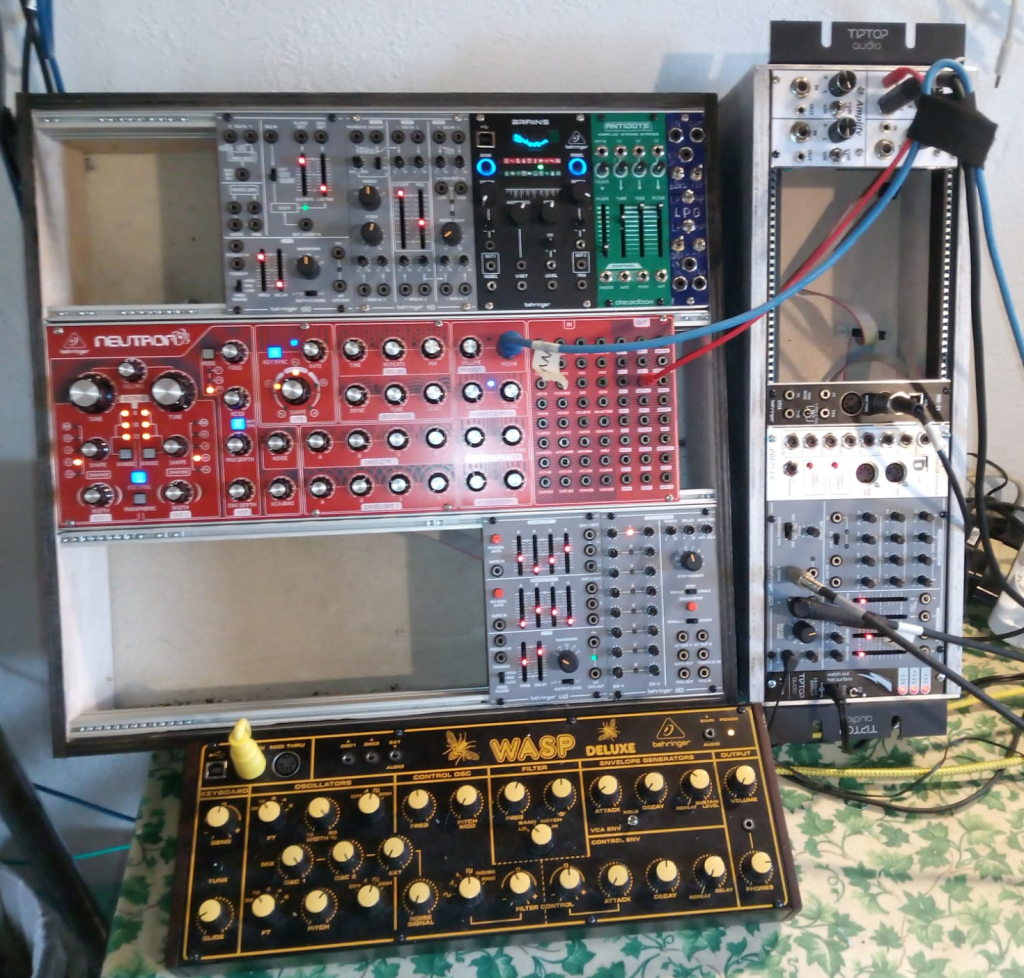
This is what the (mostly) analog (moderately) modular desk looks like now. Loads of lovely rack space!
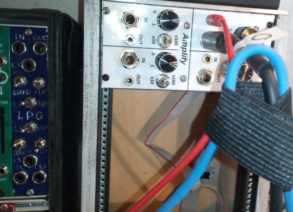
These two are modules I put together myself. First was the one on the right, two attenuators (a pot, I probably DC blocked so a couple of caps too) and two amplifiers (a couple of op amps each. I believe I used kcad for the schematic, should be around somewhere, but was pretty much datasheet stuff.
The one on the left, dual low pass gate, was very experimental. Vactrol-based, entirely passive. Surprisingly useful for very few components. The front panel was also a (failed) experiment.
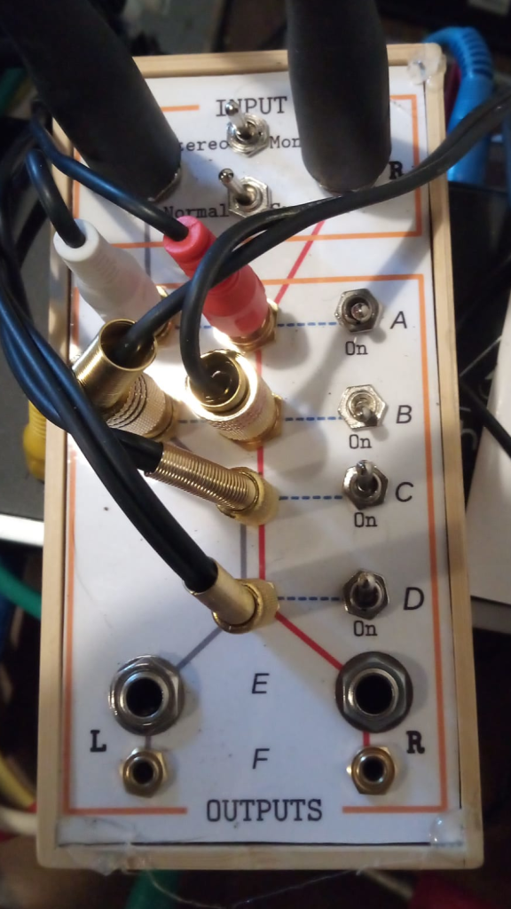
This is just a passive switch box I made to quickly change monitoring setup. Included here because the front panel technique is the one that has worked the best. Design on computer (I used LibreOffice Draw, it’s good for block diagrams etc). Do a rough printout to use as a template, cut/drill 3mm aluminium to match. Do a high quality printout on glossy paper. Laminate. Cut out and glue to the aluminium, cut out the holes with a scalpel.
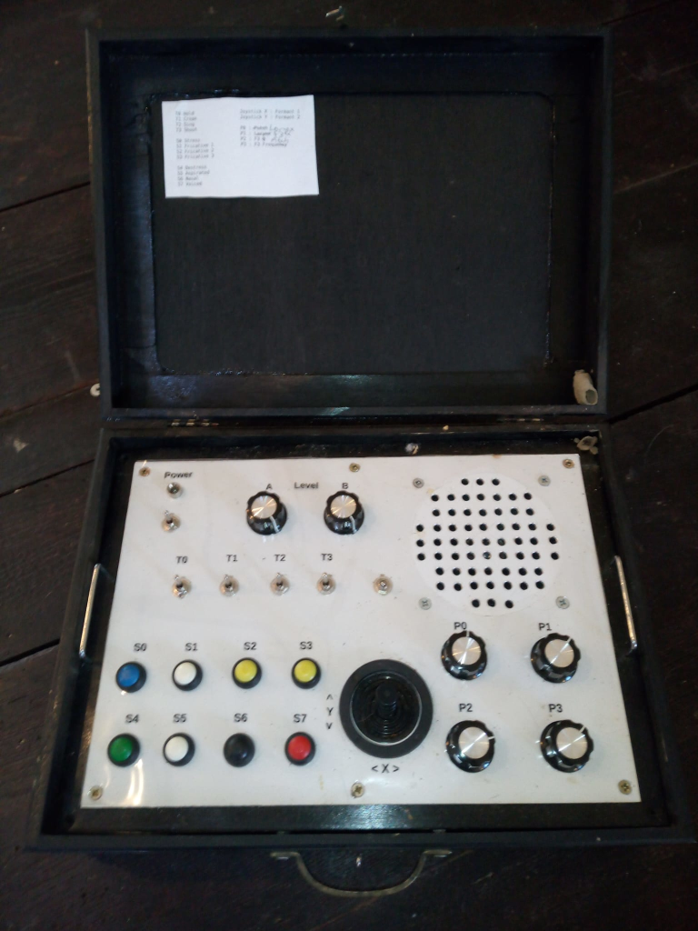
This is the Chatterbox, something I put together just before I started looking into modular. ESP32-based with decent 2-channel DAC, has MIDI in, and I even got WebSockets over Wifi going so it could be controlled from a web page. The ESP32 also has Bluetooth support, but I haven’t played with that yet).
Although I love the look, the case took way longer than I’d have liked to get together. Eurorack time!
It also revealed loads of little issues, eg. those push switches are hard work.
A bigger issue was that my code got messy. I’m not very experienced with C++ and the dual cores of the ESP32 did my head in a bit.
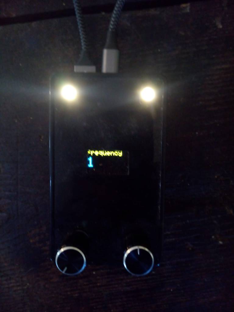
So next I made a version of another old idea, the Dreamachine. Like the Chatterbox this needed some controls and some DSP (for modulating the lights and generating white/pink noise for audio). My main aim was making a reasonably solid code framework. Instead of analogue pots I used rotary encoders and added a little display, only used the internal DACs.
I’ve got most of the coding done. The main frameworky idea was to have ESP32’s core 0 running all the UI code, core 1 doing the DSP. This seems to be working nicely, should be a good basis for other synthesis on the ESP32.
(The cable connects the device to an battery pack attached underneath).
I’ve got a bunch of analog and digital modules at various stages of design. More on those another day.
I managed to kill my main blog this week, it might take me a little while to get going. For now I’ll just point the links on my home page here.
For any poor soul interested in how I got to this :
Early Rise and fall
I did blog very regularly, it looks like 2003-2013, at dannyayers.com, on a blogging engine I wrote. The Internet Archive seems to have captured most if not all of that, but I’m pretty sure I’ll have a (RDF) data dump around somewhere.But the real world interfered, my motivation (and finances) were tidal, usually ebbing. To mix metaphors, I lost that domain name for want of a nail. I subsequently blogged occasionally somewhere here on wordpress.com (I should have the data for that somewhere too).
He is risen!
But 3 or 4 years ago I got around to getting my own virtual server again. Took a while to get it together, I lost another couple of domain names along the way. I wasn’t really thinking about blogging at the time, it was more to host services for my HKMS project(s).
Then a year or two back a friend asked me to look at reviving an old WordPress plugin (SparqlPress). Because the idea was very (sem)webby, as well as a local install of WordPress it made sense to also have one live online. I had no future plans for it so just looked for the quickest way of getting it up and running. XAMPP seemed to fit the bill, a bundle of Apache + MariaDB (MySQL) + PHP + Perl. It was very easy to set up, WordPress on top took no time.
I used that while developing SparqlPress2. It only really covers the minimum requirements for modernising the original, but is far from being properly useful. The underlying idea, of exposing the WordPress data as Linked Data, is good for both the blogger and the Web at large. I do plan to have another look, I’m sure there’s a better way of doing the architecture, but I need to think of that first.
Then I thought, as I have this WordPress install, I might as well start using it for blogging.
…and down again
If all you want is to get WordPress up and running quickly, consider XAMPP. But if you think you might ever want to use any of its components for anything else, don’t. I’ve used Apache a good few times in the past, and even though it’s .conf setup is an absolute nightmare, it seemed to make sense to use it as the entry point on my host, pointing/proxying to my other services. Which would have been fine, but XAMPP deviates from the standard Apache setup. Its filesystem locations are different and even the way the dread .confs are organised is different. I was pretty certain that at some point I’d screw up.
So as of a few months ago I’d decided to swap XAMPP for a more standard install of the necessary components. A few days ago I noticed the blog was broken.
But I’ve got a lot of other things on my plate right now and it still doesn’t seem a high priority. If I get the urge to blog, I can do it here.
I’ve just started using ChatGPT 4 as a coding assistant. Even though I’m not yet used to creating optimal prompts, it’s been incredibly good. Much faster than my usual approach of googling for something similar to what I want and tweaking it, googling at every error…
So I think I’ll build another blog engine as part of HKMS, same basic approach as the other bits. The data lives in an online SPARQL store, browser JS using templating for building requests, formatting responses.
This mini-project is a tangent to the ELFQuake project proper, to help familiarize myself with machine learning techniques & tools.
Curwen/Kodaly Hand Signals
After this occurred to me last week, I’ve made some progress in implementation. But first some background.
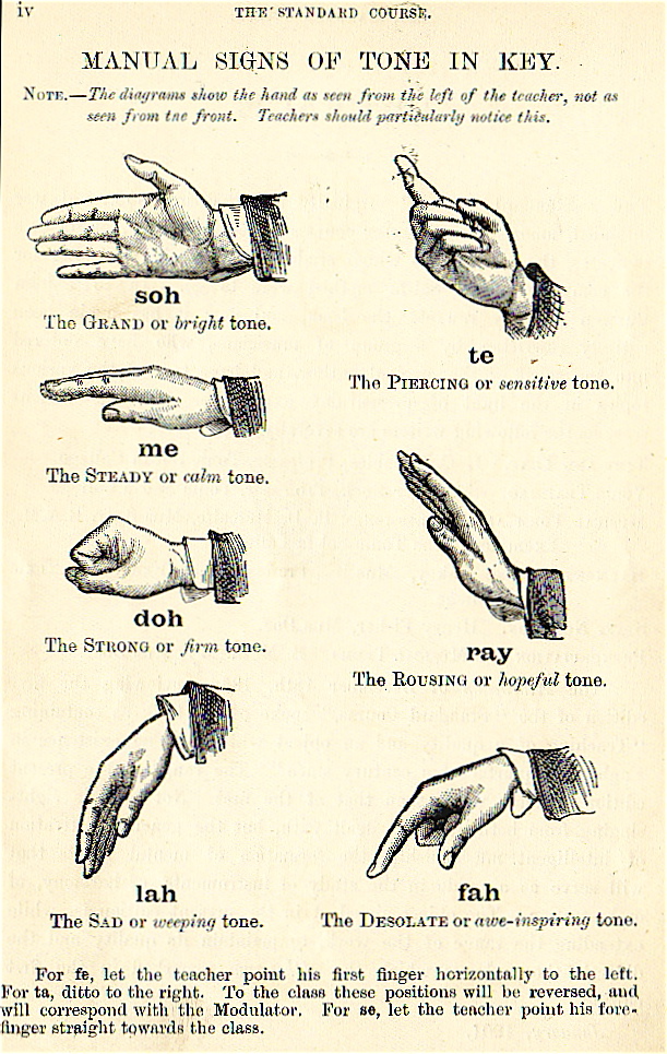
Solfège Hand Signs
Solfège, Curwen, or Kodaly hands signs are a system of hand symbols representing the different pitches in a tonal scale. They’re used to provide a physical association of a pitch system to help connect inner hearing and reading of pitches with musical performance.
For the musically inclined among you, only having 7 tones may seem a bit limited – even Close Encounter’s tune uses the do at an octave. I believe Kodaly’s extension of Curwen’s system allows a greater range by holding the sign higher or lower (I think – need to google some more). Also the semitones in between are covered. The diagram above mentions fe, ta, and se, whatever they might be. But for now 7 tones feels like plenty.
The Aim
To build a system capable of recognizing Solfège hand signals and playing appropriate tones.
Right now I’m only thinking of getting to a proof of concept, though given that I’ve got an ESP32-Cam module sitting on my shelf, and TensorFlow Lite Micro is supported, there’s potential for embedded fun further down the line.
The Plan
Acquire a lot of images of the hand signals (with associated labels)
Train a machine learning system with that data
Use the trained model to take hand signal images from a webcam and generate the corresponding tones, in real time
Let me unwrap that, starting with 2.
MNIST
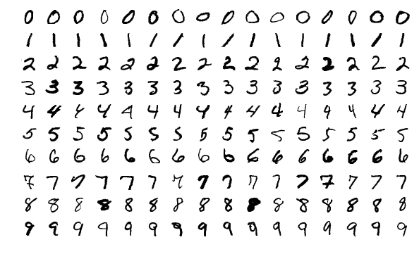
The MNIST database of handwritten digits is commonly used as a benchmark for testing pattern recognition/machine learning algorithms. It comprises a total of 70,000 images with associated labels (0-9), which looks something like this –
Typically you take the training set of 60,000 images, fire them (and their labels) at your learning system for as long as it takes. Then you use the test set of 10,000 images (and labels) to evaluate how good your system is at recognising previously unseen images.
This is isomorphic to the core of what is required to recognize hand signals.
There are a lot of systems coded up to work on MNIST. It’s hard not to see a competitive element where different algorithms are proposed that push the accuracy up a little bit further. Wikipedia lists a bunch of classifiers, with error rate ranging from 7.6% (Pairwise linear classifier) to 0.17% (Committee of 20 CNNS with Squeeze-and-Excitation Networks [?!]).
Where the code is available, it’s typically set up to allow reproduction of the results. You point say train.py at the MNIST image and label training set files, wait potentially a very long time, then point test.py at the test set files, then hopefully soon after some numbers pop out giving the accuracy etc.
While the MNIST database is ubiquitous, various limitations have been pointed out. The elephant in the room is that the fact that a particular system does exceedingly well on MNIST doesn’t mean it’ll be good for any other kind of images. This and other issues were the motivation for Fashion-MNIST, a database of more complex images.
I have absolutely no idea what kind of system topology will work well with the hand signals, they are qualitatively a lot different than handwritten digits. But, if I format my dataset as a drop-in replacement for MNIST, I can pick a wide variety of setups off the shelf and try them out, with no extra coding required (this is also the approach taken with Fashion-MNIST). Parameter tweaking will no doubt be needed, but simple trial & error should cover enough bases.
The MNIST format does look rather arcane, but it shouldn’t take me too long to figure a script to compose the data this way.
Back to the Plan part 1.
Data Acquisition
MNIST has 70,000 images. Even if I could capture one a second, this would still take about 20 hours. Noooo..!
But I’m only aiming for a proof of concept, I will consider that achieved with something like a 90% success rate. Almost ever paper you see featuring machine learning will have a chart somewhere with a curve that starts steep and quickly levels off, becoming virtually flat a little way below some desired goal.
I think it’s reasonable to assume most of the systems that can operate on MNIST-like data will have this characteristic, with size of training dataset on the horizontal axis and accuracy on the vertical.
How many sample images will be needed to get to 90%? Clearly it will depend on the algorithms, but in the general case I have no idea. Lots.
So I need to be able to capture images quickly.
After a bit of futile play trying to get a Python GUI app going I gave up (curse you Wayland!), decided to try Javascript in the browser instead. Which, after what experts might consider excessive time on StackOverflow and not enough on MDN API docs,
The capture of images from the webcam was straightforward via a <video> element (although there is an outstanding issue in that I couldn’t get the camera light to go off).
Processing, via <canvas> elements turned out to be a lot more convoluted than I expected, I didn’t find that intuitive at all. ‘hidden‘ is the keyword.
Similarly, it took me a good while to figure out a quick way of saving the final image to file (by addressing a hidden <a> element programmatically).
I started with mouse input on <button> elements but soon realised (as any fule kno) that for speed it had to be the keyboard. But that and the rest was pretty straightforward. Generating the tones was trivial, although my code might not be as considerate to the host as it could be.
A huge advantage of implementing this in a browser (aside from being able to get it to work) is the potential for crowdsourced data acquisition. I’ll tweet this!
It was pretty much an afterthought to try this on a mobile device. When I first tried it on my (Android) phone, Capture didn’t work. It is quite possible I had the camera open elsewhere, but I’m still confused why I could see the video stream. Today I showed it to Marinella on her phone, expecting Capture to fail there too. It worked! I just tried again on mine (making sure camera was off), it worked there too!
Even if it does basically work on mobile, there’s still a snag. Ok, from the desktop I can ask people to zip up a bunch of images and mail them to me or whatever. Doing things like that on a mobile device is a nightmare.
If anyone says their willing to capture a bunch of images, but it’ll have to be on mobile, I’m sure I can set something up to quickly post individual images from the application up to a server.
Onto Plan part 3.
Runtime Application
You make a hand signal to a camera, which is periodically taking snapshots. If a snapshot is recognised with reasonable certainty as being of a hand signal, the corresponding tone is played.
Implementation is very much To Be Decided, I’ve got all the data conversion & model play to do first.
Because the ML code will be built with Python, my original thought was to go with this for an application, like a little desktop GUI. I’ve since gone off this idea (blast your eyes, Wayland!). I sometimes forget that I’m a Web person.
So provisionally I’m thinking I’ll set it up as a service over HTTP. Aaron’s web.py is a fun thing I’ve not played with for a long time.
I’ve neglected this project badly. Aside from being a first-class procrastinator, I am also prone to getting overwhelmed by things. The latter is what happened here. I was at peak enthusiasm when the Kaggle Earthquake Challenge came along, coincidentally my computers all decided to fail at the same time. Not really a big deal, just needed to get things fixed, didn’t take very long. But it knocked the wind out of my sails. Just couldn’t face it at the time.
Fast forward. I’ve just had a couple of weeks knocked out by Covid, clear now. I do need to chase a contract for $$$s like yesterday, but I’m not quite up to working on someone else’s project just yet. I’ve probably got about 100 unfinished projects I could get back to, software and various lumps of electronics sitting on my shelves. But ($$$s aside), this one stands out a mile as being the most worthwhile. So now I’m ready to get back onto the horse/bicycle/crag.
The Proposition
I’m sure I’ve got something similar in this blog’s description, but the basic idea is to use machine learning to identify patterns of correlation between natural radio signals and seismic events and then attempt to make useful earthquake predictions from radio precursors. I have no illusions about this. I reckon, in the best case, very approximate predictions for a very small proportion of events is possible. It won’t be easy and it will take a lot of time. But given how cataclysmic such events can be, it’s worth a try.
The Plan
There are a handful of separate components needed, at the core: data acquisition, a model, a notification system. I think a reasonable 1000 ft view is that of a control system – inputs, processing, outputs, (validation/)feedback. All of which will need creating and tuning.
I really like fiddling with electronics hardware, have put in many hours work looking at the sensor/data acquisition parts of the system. Very poor use of my very limited cognitive resources. After a long break from this, I can shout at myself :
The novel part of this system is around the model.
I think it makes sense to narrow the geographic scope as much as possible, and ‘near me’ is an obvious choice. I live in northern Italy.
High-quality seismic data is available from the National Institute of Geophysics and Volcanology, INGV. Conveniently, the guy who literally wrote the book on natural radio signals has monitoring equipment, streaming live from up near Turin (VLF.it). Also conveniently, in an unfortunate sense, this is an active seismic region (it was the devastating quake of 2009 around L’Aquila that got me wondering about this…not to mention the one in 1920 that reduced Villa Collamandina to rubble, a village I can see from my balcony).
But I have no idea what the model should look like yet. Early on when I was thinking about this, I had a little lightbulb moment. The convolutional networks have been shown to be really efficient at pulling out salient feature from images. A human-friendly way of representing natural radio signals is as a spectrogram. Those should be receptive to reduction by off-the-shelf shape recognition algorithms. Tricky bit is the long-term temporal axis of radio & seismic data. LSTMs probably won’t hack it, but by now there’s probably an appropriate successor. (Ideally the training/application phases will be concurrent, which is a rabbit hole in my near future).
There is an advantage to putting a project on hold for a while, however inadvertent. The software equivalent of Sun Tzu’s “If you wait by the river long enough, the bodies of your enemies will float by.”. Someone else will figure out the algorithms you need.
If it really needs stating, I’m way behind the curve of developments in Deep Learning. But what I think I’ve gathered from the little experiments I’ve tried is that I can play at very small scale on my mediocre home computer (no GPU), acquire/pre-process the data, perhaps get a proof-of-concept (toy!) model topology together. Scale up onto a Cloud service.
Necessary for that is creating an environment in which to code…remembering how to code… Ok, I’m looking at Python, Tensorflow/Keras and/or PyTorch.
So before I consider even a toy version of anything earthquake-related, I need to gently paddle into the water. Last night I had a Brilliant Idea!
Zoltán who?
The prompt for this was probably Flight of the Bumblebee on the Theremin . (She did two takes – one for the sounds, one for the bee. I initially thought she’d ‘cheated’, using a MIDI theremin for note separation – nope. Just put it through tremolo, got her movements against it perfect).
With the Sol-Fa Notation (which seems better known that C, D, E… in Italy, btw), Zoltán Kodály, a 20th music teacher built on Corwen et al’s work to have kids do hand signals corresponding to their role/feeling in the scale.
Well, that would be a cool way of playing an instrument.
But naaaah! I don’t have access to the paper, but in the abstract it says they used ‘a Leap motion sensor‘. Apparently those are spatial tracking things like the IR etc. used with VR kit.
Why not just use a camera?
Grab a frame from webcam, convert it to 28×28 pixel greyscale, associate with one of the 7 labels. Use one of the models known to work well with the MNIST handwritten digit benchmark dataset. Play the Five Tones.
So I’m now in the process of building OpenCV-Python. Predictably my environment was a mess, Anaconda doesn’t seem to play well with QT/Wayland/Ubuntu.
All being well I can get a script together to tell me what hand shape to hold, a few k images within reasonable time. Find model, train, add bleeps.
I’m talking long before I get onto Tensorflow or whatever. Hey ho. Could wait forever for an environment configuration to float by (wasn’t that the whole point of VMs, Docker etc? But when you need one, float on by…).
Should be straightforward once the environment is set up. Which is the purpose of the exercise.
I nearly had kittens when danbri pointed this challenge out to me. I’ve thought for a long time earthquake prediction was well in scope for machine learning and have been dismayed at how little uptake there has been. (Surprised too, given the co-location of many tech people and the San Andreas fault…). Hopefully this competition will change things. Deadline is in 3 months, pretty significant $ prizes.
My second reaction was: “Great! I can work on ELFQuake and maybe win a prize!”. But that isn’t the whole picture. The competition is based around data generated in the lab, essentially by squashing a rock and recording its fractures. Apparently a reasonable approximation of geological effects.
I forget offhand where, but I’ve also seen a project aiming to use machine learning on real data. But that project, as with this competition, I feel is missing a trick. My gut says that although, sure, algorithms can almost certainly be useful in predicting seismic events, using the seismic data alone for training is a blinkered approach. These events, in the real world, occur as the result of the behaviour of a massively complex system. There are practical limitations on what can be modeled, but I’d suggest that it’s possible to creep a little further into the real world by bringing in data from other natural sources. For example, does the position of the moon influence the timing of events? Does seem at least credible, given that its gravity is enough to pull the oceans around.
The data source I reckon looks most promising is natural radio, signals that have been shown to sometimes contain artifacts associated with subsequent seismic events. This is the hypothesis of this project ELFQuake (ELF for Extremely Low Frequency, it’s in this frequency range and that of VLF, Very Low Frequency that earthquake precursors seem to occur).
For me, the Kaggle challenge has acted as a nudge, to get me moving on ELFQuake software again. What’s more, material has already appeared for the basic setup needed to process this data – data that has a lot in common with the ELFQuake targets. This is very convenient for me, as although I’m now getting somewhat familiar with the principles and algorithms of Deep Learning, my practical experience is virtually non-existent. So I’ve been given a great foot-up. Here’s some material using sklearn : video, github. The toolkit that seems to me the most appealing option is Keras on TensorFlow (on Anaconda), but a lot of the pre/post Python wrangling will be the same.
I’ve put my name down for the competition, it’s a bit of extra motivation – potential $$$s! – to work on this stuff, and also what I get together for it can be used as a placeholder in the end-to-end system I’m aiming for (seismic & radio sensors -> data acquisition -> [magic] -> Twitter notifications).
A good time to take stock, huddled in front of the fire.
Boo!
As is often the case, I’ve been moving more slowly on this project than I’d have liked. Lack of resources is a continuing problem, but my own tendency to procrastinate has been by far the biggest obstacle to progress. On top of this, my main dev computer packed up recently, so until I can get that fixed or replaced I’m getting things set up again on an old laptop. Frustrating.
Three Steps Forward…
My strategy of taking a multi-pronged approach has had its pros and cons. I’ve got a prototype VLF receiver mostly built and have spent quite a lot of time playing around with Arduinos and related devices. On the software side – which is really the novel aspect of this project – I did make reasonable progress, getting together a provisional system design and some of the implementation. But then stalled. My desire to build hardware to allow local data collection has been something of a distraction, when there’s nothing stopping me from working with data from INGV and VLF.it.
Plans.
Looking ahead, I really need to reboot myself on the software dev. The ultimate target for running code will be nothing more sophisticated than this laptop. But for exploring algorithms and probably NN training, pre-optimisation, I reckon using cloud services will be my best bet. Concurrently I can look at some of the side prongs that I want to include in the system as a whole – notably web publication of data and automatic generation of Twitter notifications.
As everyone that’s worked on a solo project knows, I’ve also got a lot more material in my head or at best sketched in notebooks that needs writing up. How often has the New Year Resolution been : “Write more docs.”.
Mini-Seismograph
On the hardware side, until I’ve got my income a bit better sorted out I am pretty much limited to rather a scattergun approach using what ever components I have at hand. As well as finishing off the mostly-built VLF receiver, I’ve also got the bits for a basic seismograph. It’ll essentially be :
ESP32 – microcontroller + comms : core of the subsystem, handling the acquisition and preprocessing of data, which it will expose using a basic web server, accessible from the local network (the ESP32 includes WiFi connectivity).
MPU6050 – sensors : accelerometer +gyroscope : a tiny MEMS device, connected over I2C.
MicroSD card – data logging : experience shows that 100% connectivity is implausible, so some local history is very desirable
Tiny RTC card – realtime clock : the comms will be async, so accurate local timestamps are a must.
The ESP32 is a remarkably capable little device and I’m reasonably confident of the viability of interfacing the peripherals. Hopefully just a matter of plodding through example code for each, tweaking as needed.
The MPU6050 sensors are much less sensitive than those of typical seismometers. Only events with significant magnitude are likely to be detectable. It remains to be seen, but I have my suspicions that having 2 different types of sensor in there mean it will, with a bit of wrangling, be possible to get more effective sensitivity than the individual sensor data would yield. Whatever, once the wiring and code is in place for this setup, it should be trivial to extend it to use a more sensitive sensor. (Note the Raspberry Shake 4D configuration.)
Also…
I’ve got a little tangential project on the go. ELFQuake is in essence about trying to model aspects of a physical system : Earth geology and its electronically-detectable artifacts. Creating an analogue in software that captures enough to be able to make useful predictions. Also I’m increasingly convinced that the design of analog circuits between the sensors and standard data acquisition elements (ADCs etc) will have a major impact on the potential success of the system. Putting these points together, it shouldn’t seem that off the wall that I’ve been working on the design of an analog computer. (I must admit I also want to play with chaotic systems, this is something I’ve been messing about with for years).
I’ve been a bit frustrated in recent weeks by electronic circuit design tools. The typical process is to draw out the circuit schematic, run simulations and then generate/draw PCB layouts etc. Many of the tools (especially on *nix) use SPICE format to represent the circuit topology between the different operations.
The tools I’ve looked at so far all appear to have one major flaw or another.
KiCad – the netlists it generates aren’t quite compatible with SPICE (circuit emulation) tools
Fritzing – the netlists it generate are nothing like SPICE format (I believe it uses XML)
So, the go-to representation as far as I’m concerned for pretty much anything is the Resource Description Framework (RDF). So I had a quick search around looking to see if anyone had looked at SPICE in RDF before. D’oh! I found a SPICE vocab I’d roughed out on GitHub around 2011. Jeez, my memory.
Since I did that post, JSON has become fairly ubiquitous, I’m sure it’s now most coders’ go-to representation of data. But in its basic form it isn’t Web-friendly, in the sense that it doesn’t natively support links.
Links could make things much easier to share and find: circuits, components, datasheets etc (the description of the circuit in RDF would include URLs for the components, which in turn could be associate with their characteristics, with their datasheets, etc etc).
There’s even a commercial angle. Given the list of components, a bill of materials can be generated. But typically nowadays you have to trawl through vendors to find suitable suppliers. But in RDF, the component could be associated with a vendor, with fields like the price etc. A distributed SPARQL query could figure much of this stuff out automatically.
Ok, why not use JSON? – There’s JSON-LD, which is an RDF representation, it’s JSON with links included.
One other idea. In the middle of typing this, I had a brief chat with Reto, told him what I was typing. He wondered whether there might be a role for inference (which is a good question, given the existence of RDF/OWL reasoners). Hmmm, my immediate response was, yeah, maybe something like consistency-checking a circuit for dangling wires. But Reto made the point that OWL probably wouldn’t be the best reasoning for the job, this might be more of a SHACL use case.
Off-topic. I needed to get my head into gear for work-work, and over the weekend I had an odd little idea I wanted to try. So here’s a quick & dirty write-up and video.
After playing with Arduino White Noise the other week, I did a bit of reading up on the Colors of Noise. Particularly interesting is Pink Noise, in which “each octave (halving/doubling in frequency) carries an equal amount of noise energy… This is in contrast with white noise which has equal intensity per frequency interval.”. It occurs a lot in nature, but is not entirely trivial to synthesize either using analog or digital processing. (Here’s a fairly accurate analog pink noise generator circuit).
Mind wandering, this led me onto chaotic signals. These are remarkably easy to slip into in the analog domain, essentially all you need is a non-linear system with feedback (and the right parameters) – see this old magazine write-up on non-linear circuits. They also easy to generate in the digital. The best known system is probably the Lorenz Attractor,
But there are much simpler discrete systems, notable the Logistic Map. This is just:
x1 = r * x0 * (1-x0)
where r is a constant, x0 is the current value of x, x1 the next value. With values of r between about 3.6 and 4, the thing goes chaotic.
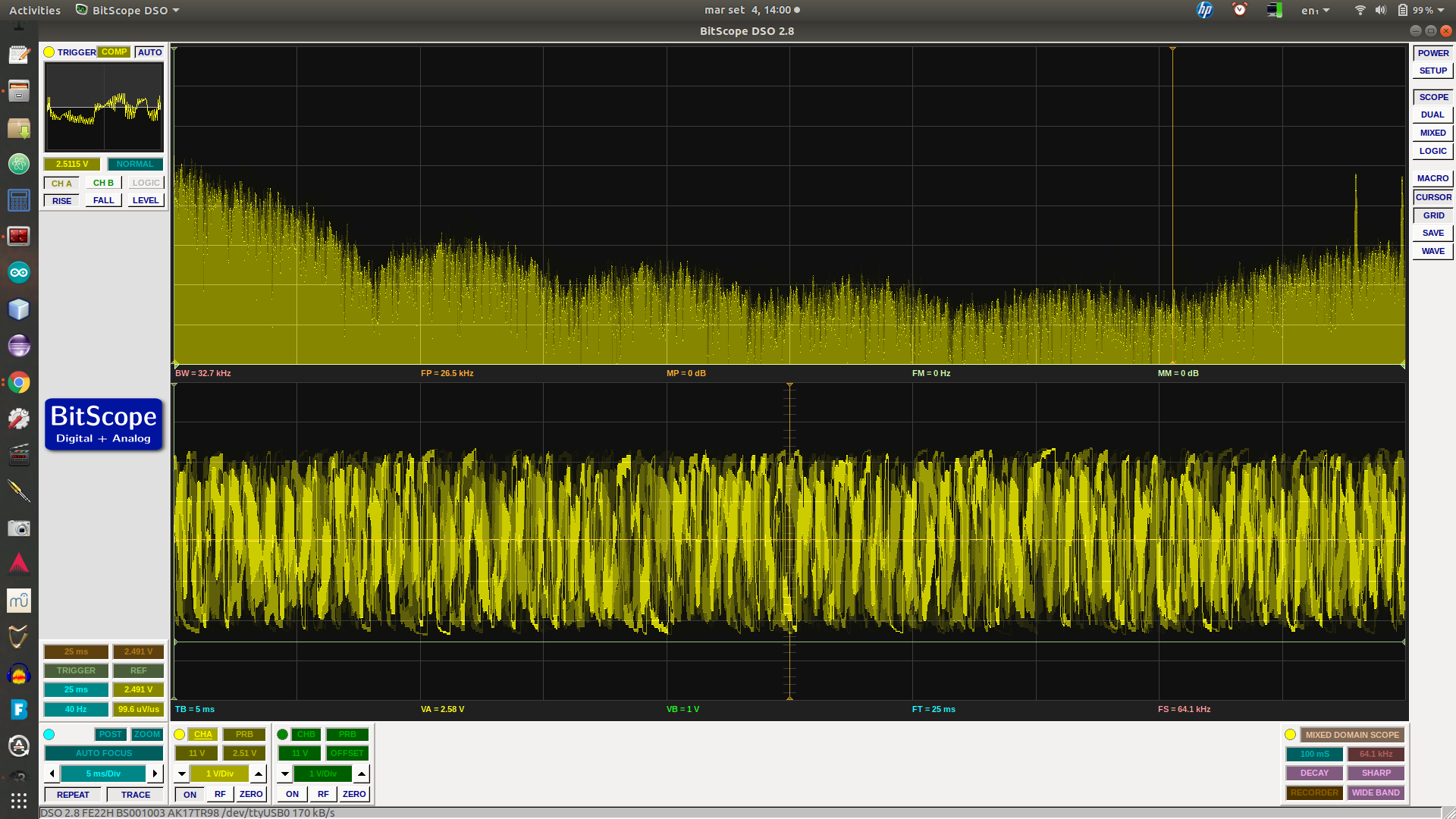
This was pretty easy to plug into the same skeleton code I used for Arduino white noise generation. The result was the same distinctive kind of racket that the analog circuits generate. To provide a bit of control, I put a pot. on an analog input, scaling the read value between 0-1 and adding it to 3 to provide an interesting value range for r.
But what I wanted to play with wasn’t just this. One way of generating electronic (and mechanic) chaos is to drive an otherwise periodic system with a periodic signal, as in the chaotic double pendulum. But with pink noise on my mind, I was curious to see what would happen if a chaotic system was driven with white noise.
The code, again using the skeleton I already had, was straightforward. I added another pot. to another analog input to determine the level of the noise signal.
My code is a real hacky mess at the moment, mostly due to hopping between integer and float values, and scaling, but the core of it looks like this (effectively inside a loop):
  // Shift register-based random number generator (white noise)
  unsigned lsb = lfsr & 1;   /* Get LSB (i.e., the output bit). */
  lfsr >>= 1;                /* Shift register */
  lfsr ^= (-lsb) & 0xB400u;

  // control values
  noise_level = analogRead(NOISE_LEVEL_PIN); // will be 0 - 1023
  r_value = analogRead(R_VALUE_PIN);

  r = 3 + ((float)r_value) / 1024;

  noise_scale = ((float)noise_level) / 2048;

  x_scale = 1 - noise_scale;

  noise = noise_scale * ((float)lfsr) / 65536;

  x = x_scale * x + noise;

  // logistic map
  x = r * x * (1 - x);


  // the value to output
  temp3 = (uint16_t)(x * 65536); // scale & cast
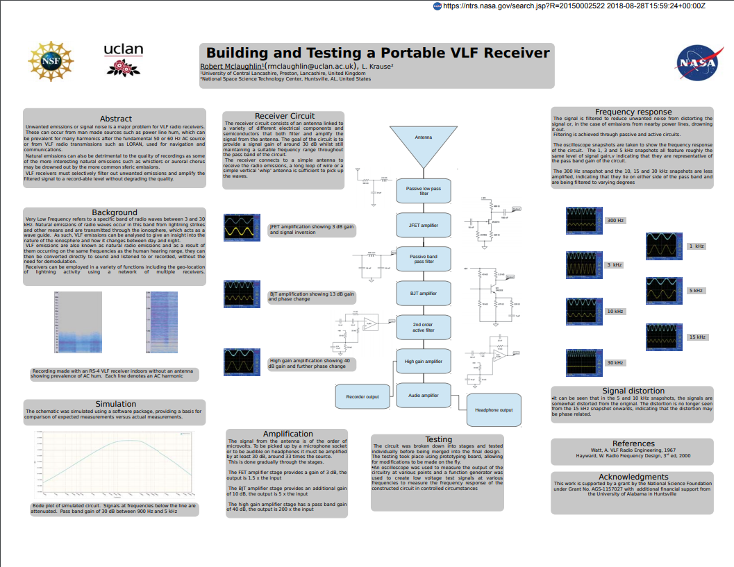
I’m doing a little more on a simple handheld VLF receiver I’ve been working on. For an electric field receiver all that’s essentially required is a whip antenna and a high input impedance, high gain, audio frequency amplifier. Some filtering is desirable to limit the bandwidth and cut the noise of mains hum.
I’ve already soldered up the input & filter stages, yesterday breadboarded the output stage – an amplifier to drive a little speaker/headphones. But I’d forgotten a key consideration, how much overall gain the thing should have.
It doesn’t have the schematic – I expect it’s one of their INSPIRE models. But it does have what I was looking for. Signal is of the order of microvolts, their overall gain is x1500 – rather more than I’ve allowed for so far. There’s a feedback resistor change in my near future.
First though I reckon I’ll draw up the circuit as it stands (in KiCAD). I can figure out the gain bits from there, and simulate. I also need to check roll-off at the frequency extremes (call it 20Hz & 20kHz). Hmm, gain of 1500, that’ll be tempting to stability problems.
When I was looking for the gain requirements yesterday, I opened a bunch of the results in browser tabs. I found what I was looking for in the first, but am pleased I didn’t close the others. While vlf.it is the site for all things Radio Nature, I did stumble on some material I hadn’t seen before.
This page is notable : VLF Natural Radio Reception at techlib.com. It features a variety of simple receiver designs. One piece of utter genius jumped out at me. The major problem with VLF reception is interference noise, so ideally you want to situate the receiver a long way from sources of that – eg. houses, computers… Which is a pain if you want to record/analyze the signal. Here the author bends a baby monitor transmitter, replacing the mic with a VLF preamp. Voila, instant remote receiver.
I love this :
“The antenna was horizontal and near the ground under my truck for this recording. That turned out to be a questionable location, by the way! Not only did several neighbors become alarmed by it, but a couple of police officers also spotted the thing. I must admit, it does have a bomb-like appearance! It spent the rest of the night under an overturned flower pot with the VLF antenna sticking out the little drain hole in the bottom.“.
Another very promising site I ran across, have still to read, is Larry’s Very Low Frequency Site. Looks like there’s some good material.
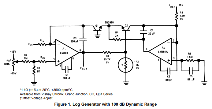
I’ve been looking at analog log/exp converters, primarily with music synth applications in mind. Here’s a typical Voltage Controlled Oscillator circuit, which uses a pair of transistors as part of the exponential conversion sub-circuit. But there may well be potential for using an analog log converter to effectively improve the resolution of the ADC part of a seismic data acquisition system. Note that earthquake magnitude measurements are usually expressed as log values – e.g. in the Richter Scale, a magnitude 5 event has an amplitude 10x that of a magnitude 4 event.
There’s a useful selection of general-purpose log & exp converters in TI Application Note AN-30. When building such circuits from op amps + transistors, there are two factors that can significantly affect accuracy. The first is the effect of temperature on transistor characteristics. This is usually offset by using a temperature-sensitive (‘tempco‘) resistor. I don’t currently have any of these… The second issue is that the circuits generally involve a pair of transistors in a balanced configuration. Here it’s useful to select transistor with closely matched characteristics.
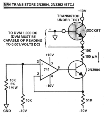
More sophisticated variations are described at Music from Outer Space. I’ve got a bag of 100 2N3904 transistors (about €2 from China), so I decided to have a go at finding some matched pairs.
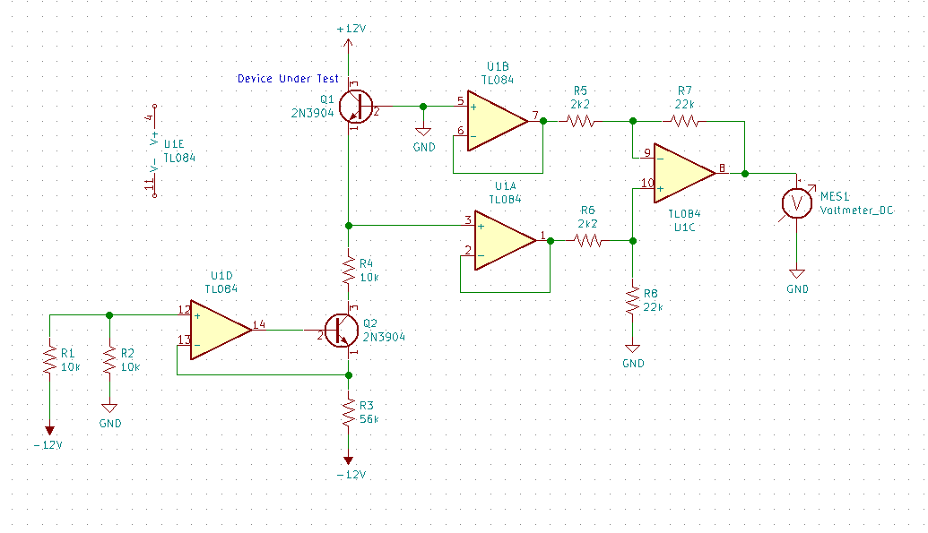
My circuit began with a silly mistake. I’d misread Moog’s circuit, thinking that both test points were floating, not noticing that one was ground. I only realised once I’d got the thing breadboarded. No big deal, and buffering both lines did offer a bit more scope for experimentation. This is what I ended up with:
I used KiCAD for the diagram, files are on github.
The left-hand side is the same as Moog’s, just with a better op amp and 1% resistors. The right-hand side is a basic instrumentation amplifier consisting of a couple of unity-gain buffers feeding a differential amplifier with gain of 10. I initially tried a gain of 100 (using 220k rather than 22k around U1C), with a bias voltage (from a pot) on pin 5 of U1B, but this turned out to be over-sensitive, it was too easy to flip the output to one rail of the other.
I didn’t see much point in accurate reference voltages as in the MFOS designs, my 12v is regulated and after I’d left everything connected for a little while, there was too much variation in individual measurements.
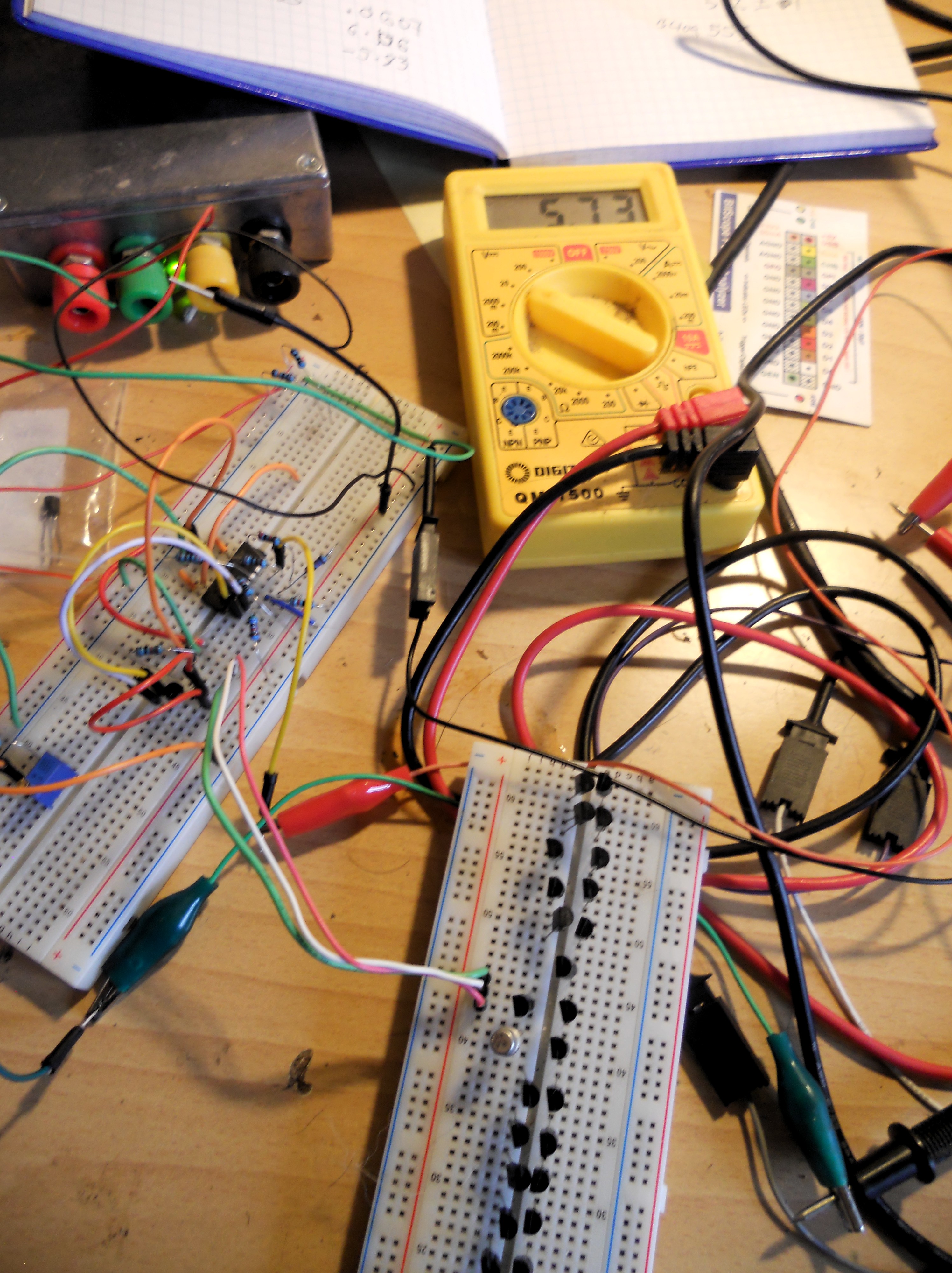
To do mass comparisons while avoiding touching the transistors (and warming them up), I stuck 40 of them into a breadboard:
Moog refers to Vbe values of around 0.6V, and a target of matching within 2mV. I got similar values, 0.573 +/- 0.001V with only a couple of exceptions (even then less than 3mV difference). This seemed a little too good to be true, so I played around with things like changing the bias voltage, but still the values did seem surprising closely matched. Then a simple sanity check occurred to me. Putting a BC109 under test, this gave a value of 0.553V. Not matched to the 2N3904s.

